
Integrated Rotary Joint Selection Guide for Industrial Automation OEMs
Introduction
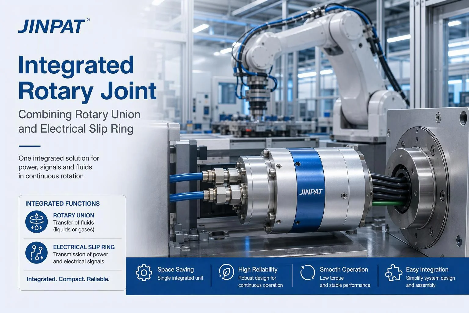
An integrated rotary joint is a multi-passage rotary union with optional slip ring integration: one coordinated assembly that carries fluid or gas channels, and where required electrical power and signals, across a rotating interface. OEM engineers should evaluate fluid passages, electrical transmission, mechanical integration and operating conditions together, because sealing, bearing support, cable routing and rotational duty interact in a single structure rather than as independent components.
In automation systems, the integrated rotary joint sits at the point where a machine frame meets something that turns: a robot wrist, an indexing table, a roller, a tool spindle or a turret. Its role is to keep media and electrical circuits continuous through unlimited rotation, so the machine avoids wrapped hoses, twisted cable looms and the maintenance that follows them.
The scope of this guide is deliberately narrow. A rotary union transfers fluid or gas between stationary and rotating parts. A multi-passage rotary union may carry several independent channels, depending on its configuration. An electrical slip ring transfers power and signals across a rotating interface. An integrated rotary assembly may combine both within one housing. Not every rotary union includes a slip ring, and not every integrated assembly supports every combination of electrical, pneumatic and hydraulic function. Treating these as interchangeable terms is the most common source of mis-specified enquiries.
This guide covers the applications where integration is worth considering, the media and duty information a supplier needs, seal and bearing decisions, leakage acceptance, materials and environmental protection, slip ring integration including EMC and isolation, hose and cable loads, maintenance access, customised design, validation, and the UK and EU compliance questions that arise for European OEMs.
The subject matters commercially as well as technically. European OEMs sell machines into multiple markets, so a rotating transmission assembly specified for a German line may also need documentation for a British one. Reliability and safety expectations are high, and where equipment is intended for potentially explosive atmospheres, ATEX or UKEX requirements may apply. CE and UKCA marking questions depend on the product and destination market. None of these frameworks is automatic, and each is examined later in the guide against the actual conditions that trigger it.
Read the sections in sequence if you are at the concept stage, or move directly to the selection criteria and slip ring integration sections if you already have a duty profile.
Applications
An integrated rotary joint may be considered when automation equipment must carry more than one transmission function across a rotating interface — for example compressed air for gripping plus power and signals for sensors. The required media, the number of independent channels and the machine's movement pattern determine whether an integrated rotary assembly is appropriate, or whether separate components suit the installation better.
Robotics and EOAT
In a robot wrist or end-of-arm tooling, the rotating interface typically carries compressed air for gripping or vacuum, electrical power for tools and sensors, and sometimes hydraulic pressure for high-force actuation. Signal transmission for tool identification, force sensing or vision may share the same interface. Compact installation is usually the binding constraint, because the wrist envelope limits both the union body and the cable and hose exits. Rotation range, cable routing and hose bend radius therefore drive selection as much as pressure and current do.
Indexing Tables and Packaging Lines
Indexing tables and packaging lines usually need electrical power and control signals at the rotating station, plus pneumatic functions for gripping, ejection or forming, and process fluid where filling or dosing is involved. Intermittent indexing with frequent start-stop cycles places different demands on bearings and seals than continuous rotation does. Where washdown is part of the cleaning regime, enclosure protection and material choice become selection criteria in their own right.
Machine Tools, Printing and Process Rollers
Machine tools, printing presses and process rollers use rotating connections for coolant, hydraulic clamping, thermal fluid, compressed air and electrical services on the rotating drum or spindle. Operating conditions often include sustained rotation, thermal variation and mechanical loads transmitted through the shaft. Mechanical interface accuracy, runout and mounting stiffness matter here, and the transmission requirements should be mapped against the machine's actual duty rather than assumed from the machine category.
Selection Criteria
Integrated rotary joint selection begins with the required transmission media and duty profile. Engineers should define pressure, flow, rotational speed, sealing, bearing loads, leakage limits, material compatibility and environmental conditions before deciding on the assembly configuration, because each of these inputs constrains the others and a late change to one usually reopens the rest.
Media and Duty Profile
Start with the medium itself: air, water, oil, hydraulic fluid, coolant or another process fluid, and its compatibility with the wetted materials. Then record the number of independent passages, operating pressure, required flow, media temperature and rotation speed. Continuous versus intermittent rotation, start-stop frequency and duty cycle change seal and bearing duty. A written duty map — the sequence of rotate, hold, grip and release with timings — is the most useful single document you can give a supplier.
Seals, Bearings and Leakage Limits
Seal material must suit the medium, its temperature and the pressure it sees; different media may need different seal materials and internal arrangements, and should not be assumed to share one passage. Bearing arrangement and mechanical support must carry the radial and axial loads the application imposes, including hose pull. Leakage expectations should be written as acceptance criteria before procurement, distinguishing normal operating requirements from manufacturer-defined limits and from your own project-specific pass/fail values. Inspection and maintenance access belongs in the same decision.
Materials, Environment, IP and ATEX
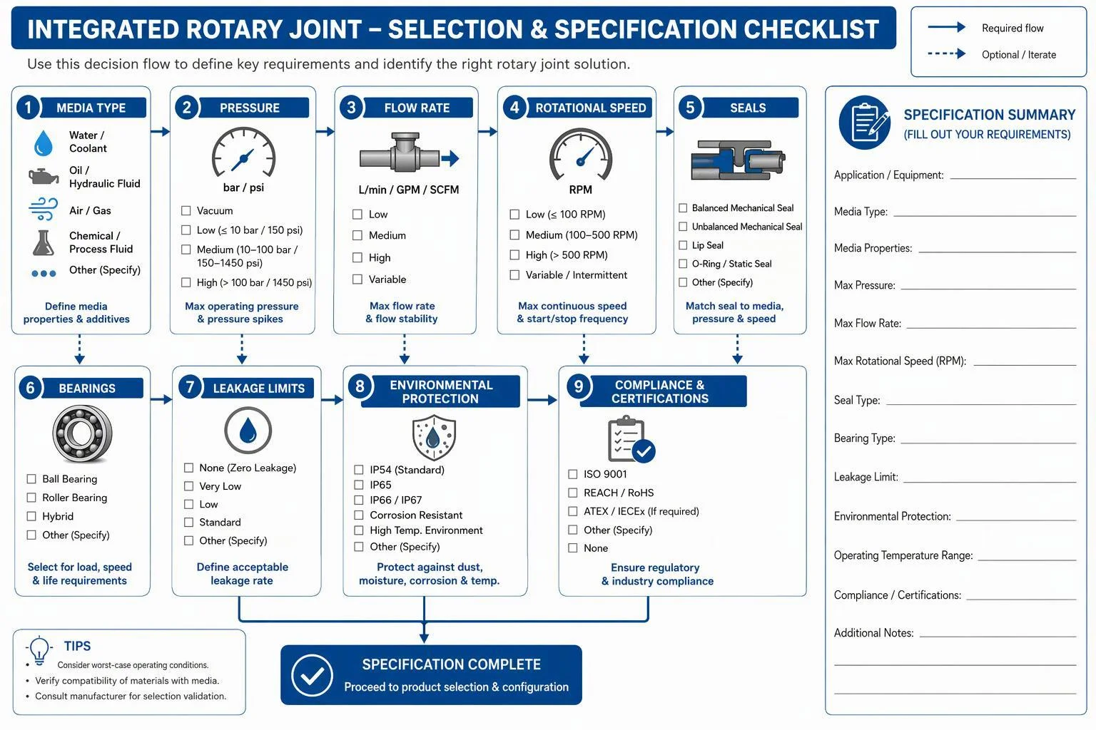
Material and enclosure selection follows the installation environment: corrosion and chemical exposure, dust, water, washdown, ambient temperature, vibration and mechanical shock. Specify the IP rating the installation actually demands rather than treating a rating as a universal product property, and note that an IP rating alone does not establish suitability for every harsh environment. ATEX and UKEX are separate questions, relevant only where equipment is intended for potentially explosive atmospheres; general environmental protection is not hazardous-area certification.
Integration with Slip Rings
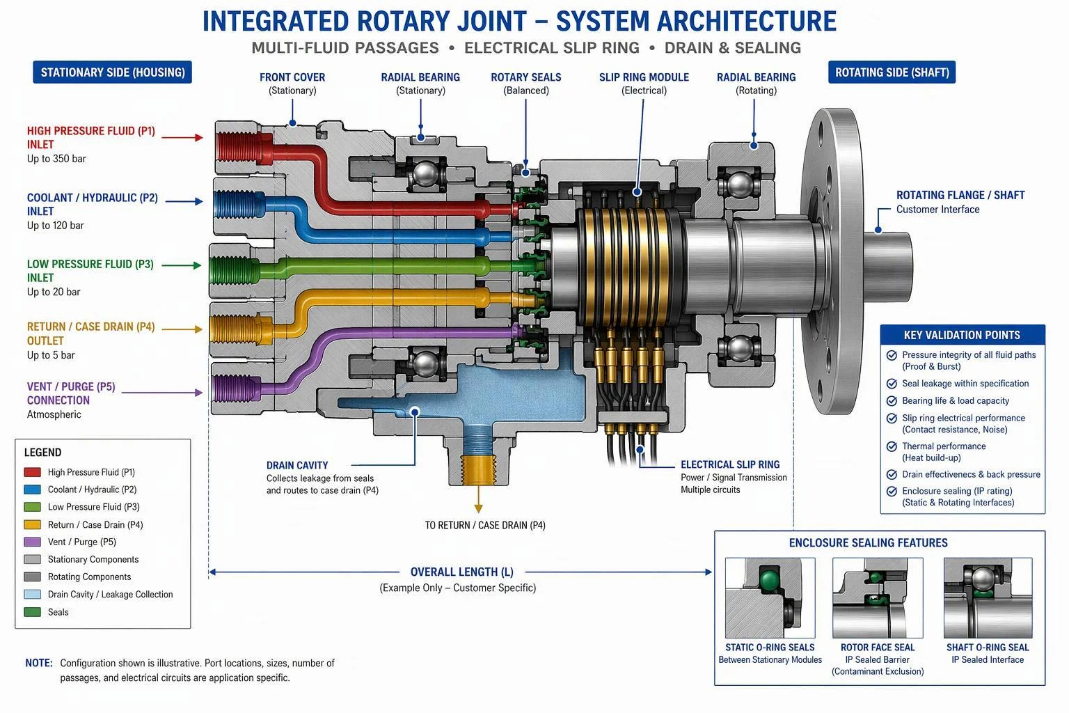
An electrical slip ring can be combined with a multi-passage rotary union when a machine needs both electrical transmission and fluid or pneumatic transfer across the same rotating interface. The configuration depends on electrical, mechanical, sealing and installation requirements together, so the electrical specification and the fluid specification should be developed in parallel rather than sequentially.
EMC and Isolation
Power circuits and signal circuits should be separated and their shielding and grounding defined, since a shared return path can degrade signal integrity. EMC considerations apply to the whole assembly: cable exits, enclosure continuity and the routing of power alongside sensitive signal lines. Electrical isolation requirements — between circuits, and between circuits and the housing — should be stated explicitly, together with the insulation and continuity checks that will demonstrate them at acceptance.
Hose Loads and Rotating Mechanics
External hoses and cables exert real loads on a rotating assembly. Bend radius, connection orientation and the stiffness of the mounting all determine how much radial and axial force reaches the bearings. Alignment between the rotating and stationary sections, rotational clearance and freedom from mechanical interference should be checked at the design stage, not at commissioning. Treat hose and cable loads as part of the complete rotating assembly design rather than as unrelated installation details.
Monitoring and Maintenance
Maintenance planning should cover leakage monitoring, pressure and flow monitoring where applicable, seal and bearing inspection, electrical connection inspection, and the condition of cables and hoses. Contamination and corrosion are the failure modes most easily missed during routine checks. Maintenance access and replacement planning should be agreed early, because an assembly that cannot be reached for inspection will be run until it fails. Intervals depend on manufacturer instructions and actual operating conditions; no fixed figure applies across applications.
JINPAT provides integrated electro-pneumatic slip ring solutions for harsh-environment applications.
Customised Design and Validation
Customised integrated rotary joints may be necessary when standard configurations cannot meet the required passage layout, mechanical envelope, electrical interfaces, sealing or environmental conditions. OEM engineers should define the complete application specification and agree validation and documentation requirements before final design approval, since changes made after that point tend to affect seals, bearings and electrical modules together. OEM engineers and the supplier should agree project-specific acceptance criteria for leakage, electrical performance, mechanical operation and environmental protection where relevant; a change to passages, seals, bearings, enclosure or electrical module reopens the affected validation for re-evaluation.
Envelope, Mounting and Interfaces
Define overall dimensions and the installation envelope, through-bore and shaft requirements, mounting and flange interfaces, and the layout of fluid passages. Electrical connections, cable and hose exits, mechanical clearances and maintenance access belong on the same drawing set. A change to any one of these — an extra passage, a larger bore, a different exit angle — usually propagates into the housing, the seal stack and the electrical module, so the interface drawing should be the controlled document for the project.
UKCA/CE, PESR and UKEX/ATEX
UKCA and CE relevance depends on the destination market and the applicable product regulations. In Great Britain, the Product Safety and Metrology etc. (Amendment) Regulations 2024 continue recognition of CE marking for many product areas, so businesses may generally choose between UKCA and CE for those goods; CE remains the route for the EU market. Pressure equipment falls under the Pressure Equipment (Safety) Regulations 2016 in Great Britain and Directive 2014/68/EU in the EU, both applying above 0.5 bar maximum allowable pressure, with classification depending on the equipment, pressure and fluid group. For hazardous areas, UKEX applies to the GB market and ATEX Directive 2014/34/EU to the EU. Component documentation does not by itself make the complete machine compliant; that remains the machine manufacturer's responsibility.
Hygiene and Documentation
In packaging, filling and food-processing equipment, specify cleanability, seal and material compatibility, drainage and moisture management, then agree the documentation package: general arrangement and interface drawings, electrical and fluid diagrams, installation and maintenance instructions, inspection and validation records, and applicable conformity documentation. Where food contact is claimed, request supporting evidence rather than assuming it.
Conclusion
An integrated rotary joint is selected by working from the application outward: define the media and duty profile first, then evaluate seals, bearings and leakage limits, decide whether slip ring integration is needed, confirm the mechanical envelope and environmental protection, and agree validation and compliance documentation before design approval. That sequence keeps the electrical, fluid and mechanical requirements in one specification rather than three disconnected ones.
Before requesting a quotation, prepare a duty map covering each passage, its medium, pressure, flow and temperature, plus rotational speed, continuous or intermittent operation, start-stop frequency and rotation direction. Add a short application and machine description, the seal expectations, the project quantity and schedule, the electrical circuits with current, voltage and signal type, the installation envelope and mounting interfaces, hose and cable routing, ambient and washdown conditions, and any hazardous-area or pressure-equipment classification that may apply. State leakage limits and acceptance tests explicitly, because a supplier cannot quote against an unstated criterion. Attach drawings and a duty map where available.
Compliance and hygiene expectations belong in the same package. Identify the destination market so UKCA, CE, PESR, PED, UKEX or ATEX applicability can be assessed against the actual equipment rather than assumed, and request the drawings, circuit and passage diagrams, installation and maintenance instructions, inspection records and conformity documentation the project requires. Where the machine is hygiene-sensitive, describe cleaning exposure and drainage needs so seal and material choices can be reviewed.
Primary CTA: contact JINPAT to discuss an integrated rotary joint application and request an engineering review.
Secondary CTA: submit your application drawings, media requirements, operating conditions and electrical specifications to request a suitable product recommendation or quotation.

