
Slip Ring Assembly Design Guide for OEM Engineers
Quick Answer: How Should OEM Engineers Design and Specify a Slip Ring Assembly?
Slip ring assembly design should start from the complete machine requirement, not one electrical rating. OEM engineers should define power circuits, signals and data, rotor and stator interfaces, rotational duty, mechanical support, cable routing, thermal conditions, environmental exposure, validation requirements and maintenance expectations before deciding whether an existing configuration or a custom slip ring assembly is appropriate. A slip ring assembly is both an electrical and a mechanical integration problem, and the two must be reviewed together.
Key Takeaways
Define the electrical architecture circuit by circuit, not as one total current figure.
Separate continuous, peak and signal requirements, and state which circuits are affected.
Fix the rotor and stator mechanical interfaces before final product selection.
Treat bearings, alignment, mounting and cable routing as part of the assembly design.
Review power, signals, industrial data, shielding and grounding as one system.
Evaluate thermal, rotational, vibration and environmental conditions from real machine data.
Decide whether a standard configuration fits or OEM customization is required.
Agree validation and acceptance requirements before design approval.
Prepare complete drawings and specifications before requesting engineering review or quotation.
1. What Is Included in a Slip Ring Assembly?
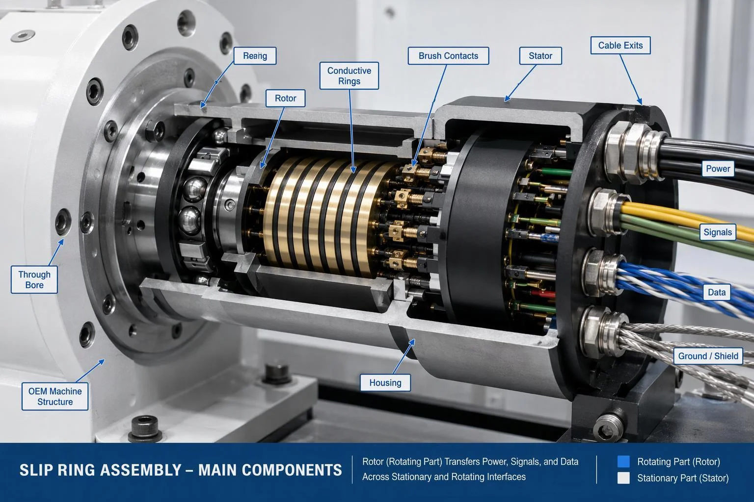
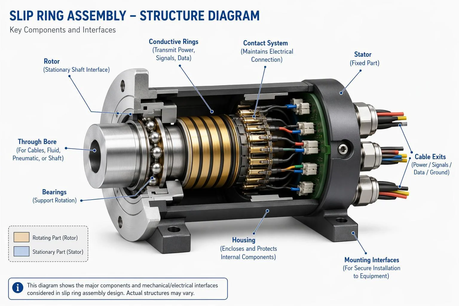
A slip ring assembly is the complete rotating electrical interface, not only the conductive rings and brushes. Depending on the design, it may include a rotor, stator, conductive rings, contact elements, bearings, shaft or through-bore structure, housing, seals, electrical leads, connectors, grounding provisions and the mounting interfaces needed to fix the unit into an OEM machine.
Rotor and Stator
The rotor is the section that turns with the machine; the stator is the section held stationary. Which side rotates is set by the machine architecture, not by the slip ring, so define attachment points, torque restraint and cable or connector interfaces on both sides early. Without clear torque restraint, cables or brackets can end up carrying rotational load.
Conductive Rings and Contact System
Conductive rings and contact elements form the power and signal paths across the rotating gap. Contact architecture varies by design, and material and wear behaviour depend on current, speed, duty and environment, so no single contact material is universally superior. Specify the electrical duty and let the supplier match the contact system to it.
Bearings and Mechanical Support
Where bearings are used, they support the rotating structure and react radial and axial loads, so alignment and mounting stiffness matter. Decide how much support the machine shaft provides and how much the assembly must provide itself. A slip ring is generally not intended to carry the weight of connected equipment or absorb unsupported shaft loads.
Housing, Seals, Cables and Connectors
The housing carries the stationary structure and, with seals where fitted, shields the internals from the environment. Cable exits, connector orientation, strain relief and service access all constrain the mechanical envelope, so state them in the requirement set rather than leaving them to installation.
2. What Requirements Should Be Defined Before Designing the Assembly?
Build a complete requirement set before choosing the architecture. It should cover electrical circuits, signals and protocols, rotational speed and motion profile, installation envelope, mounting, environment, service access, expected duty and validation criteria, so the supplier can evaluate the whole rotating interface rather than an isolated product specification.
Electrical Load Definition
List circuit quantity, current per circuit, continuous current, peak or inrush current where relevant, voltage, AC or DC operation, simultaneous loading, and protective earth and grounding requirements. A single total current figure hides which circuits carry what, and it cannot be used for engineering review.
Signal and Data Requirements
Name each signal type: analog, digital, encoder, CAN, RS-485, Industrial Ethernet, EtherCAT where required, and any application-specific interface. "Data" alone is insufficient, because each protocol may impose different cable, shielding, grounding and signal-integrity requirements on the assembly.
Mechanical and Integration Profile
Record the through-bore requirement, shaft diameter, maximum outside diameter and overall length, flange or housing interface, which side is fixed and which rotates, cable exit direction, connector requirements and available maintenance space. These dimensions decide whether a candidate assembly can physically enter the machine.
Environment and Operating Duty
Describe rotational speed, continuous or intermittent rotation, oscillating motion, start-stop frequency and duty cycle, plus ambient temperature, dust and water exposure, vibration, shock, and corrosion or chemical exposure. These are machine conditions, and they should be recorded as measured or expected values rather than assumed.
3. How Should the Electrical and Thermal Architecture Be Designed?
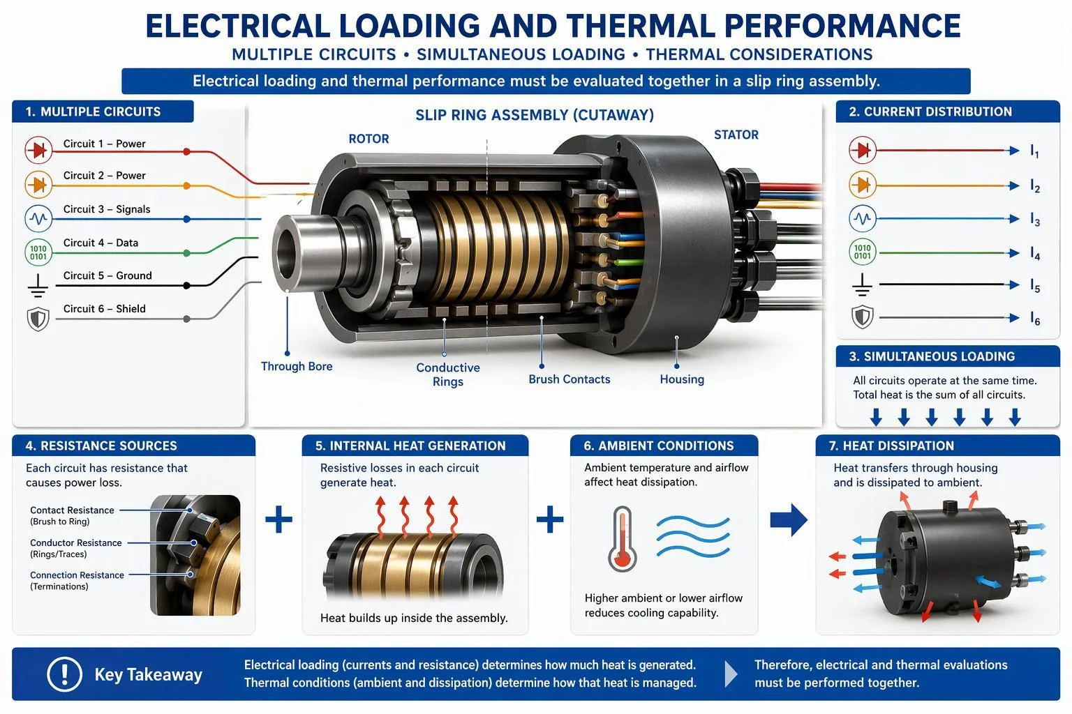
Evaluate the electrical architecture circuit by circuit and alongside the thermal conditions. Current distribution, voltage, conductor and contact resistance, simultaneous loading, duty cycle, ambient temperature, enclosure conditions and available heat dissipation all influence the final slip ring assembly design.
Current Distribution and Circuit Architecture
Group circuits by function and current level, and note which loads run at the same time. One assembly may carry several current levels, shared and independent functions, and spare circuits reserved by the OEM design; each group needs its own entry in the circuit table.
Continuous, Peak and Inrush Current
Continuous current is the steady load; peak and inrush are temporary conditions. For each, state magnitude, duration, repetition and the affected circuits. Maximum current alone is insufficient, because a short repetitive surge and a sustained load stress the assembly differently.
Resistance and Heat Generation
Conductor resistance, contact resistance and connection resistance all convert electrical energy into heat inside the assembly. When several loaded circuits run simultaneously, that heat accumulates, so the thermal review should use the real simultaneous loading pattern rather than one circuit in isolation.
Thermal Conditions and Derating
Ambient temperature, an enclosed installation, nearby heat sources, restricted airflow, duty cycle and multiple heavily loaded circuits all shift the thermal balance. Treat derating as an application-specific evaluation agreed with the supplier; do not apply a universal percentage that was never validated for your conditions.
Insulation and Electrical Isolation
Define which circuits must stay isolated, how power is separated from signal paths, and where grounding and protective earth connect. Electrical safety requirements set by the customer or by applicable standards belong in the specification; creepage, clearance, insulation resistance and dielectric values should come from those requirements, not from assumption.
4. How Should Power, Signals and Industrial Data Be Integrated?
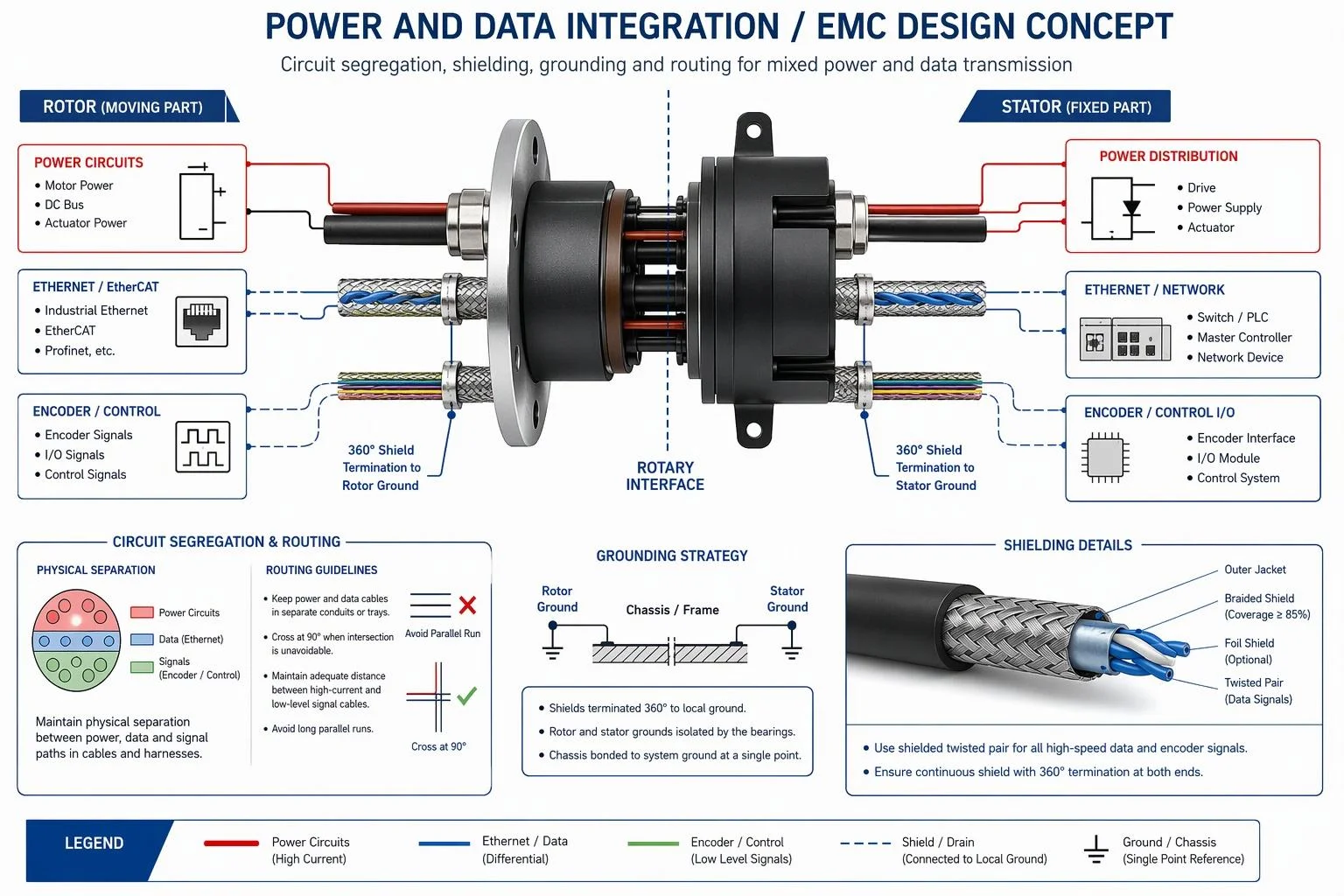
Mixed power and signal assemblies need deliberate circuit segregation, grounding, shielding, cable routing and communication specification. Identify each signal type and protocol rather than requesting data transmission in general, because Ethernet, EtherCAT, encoder, CAN and other interfaces may impose different electrical and signal-integrity requirements.
Power and Signal Segregation
Keep noise-sensitive channels apart from power and switching circuits where the design allows, through circuit grouping, physical spacing and separate cable routing. Grounding and shielding decisions belong to this layout step, not to a later fix after the assembly is built.
Ethernet and EtherCAT
State the required network interface, data rate, cable and connector specification, and controlled impedance where applicable. Return loss, BER, jitter or skew criteria apply only where the actual interface makes them relevant. EtherCAT uses standard IEEE 802.3 Ethernet frames, and shielded twisted pair is the standard EtherCAT cable type, so shield and grounding treatment belongs in the requirement.
CAN, Encoder and Control Signals
For CAN, encoder and control channels, define signal type, channel quantity, differential or single-ended signalling, encoder architecture, signal frequency, cable characteristics, and grounding and shielding. These parameters let the supplier judge whether the channel can be carried reliably through the rotating interface.
Shielding, Grounding and EMC
Plan shield continuity, grounding strategy, bonding, shield termination and power cable routing during architecture design. Industrial installation practice treats shield earthing as a defined method rather than an afterthought, and grounding approaches vary with the plant, so agree the strategy for the complete machine and validate it under representative operating conditions.
Electro-Optical or Other Hybrid Architectures
Hybrid architectures combine electrical power with optical transmission, or add fiber-optic rotary interfaces where high-bandwidth, interference-resistant communication is required. Specify hybrid transmission only when the actual assembly design supports it; not every slip ring assembly integrates optical channels, and the electrical, optical and mechanical interfaces must be reviewed together.
5. How Should the Rotor, Stator and Mechanical Interfaces Be Designed?
A slip ring assembly must fit the machine's mechanical architecture as precisely as its electrical requirements. OEM engineers should define the rotor and stator relationship, through-bore or shaft configuration, mounting method, alignment, bearing support, cable routing, rotational clearance, torque restraint and service access before finalizing the assembly.
Through-Bore, Solid-Shaft and Flange Configurations
Through-bore assemblies pass a shaft, pipe or cable bundle through the rotating interface; solid-shaft arrangements mount on a shaft end; flange and housing-mounted versions attach to a bracket or machine frame. Each configuration changes the available envelope, mounting-hole pattern and access, so state the machine interface rather than a nominal size alone.
Rotor and Stator Interface
Identify which side rotates and which stays stationary, then define the attachment points and torque restraint for each. Without a positive restraint, the stator can be dragged by rotation, and cables may become unintended structural or torque-carrying elements.
Bearings and Alignment
Where the assembly includes bearing support, machine shaft alignment, radial and axial loading, mounting stiffness and concentricity all affect mechanical stability. Clarify whether the machine or the slip ring assembly carries the rotating load; the assembly is not a substitute for machine shaft support.
Cable and Connector Routing
Define rotor-side and stator-side cable exits, connector orientation, available installation space, strain relief and bend radius. Secure leads so they do not suffer friction, side loading or pull during rotation, and confirm that connector access remains possible after the assembly is mounted.
Maintenance Access
Plan inspection, replacement and cable access before the design is fixed. Space needed for servicing, and the machine disassembly steps required to reach the assembly, influence mounting choice as much as the electrical specification does.
6. How Do Rotational Duty, Vibration and Environment Affect the Assembly?
Mechanical duty and operating environment can significantly influence the slip ring assembly architecture. Rotational speed, oscillating motion, start-stop cycles, vibration, shock, temperature, dust, water, chemicals and corrosion exposure should be specified as real machine conditions so the assembly can be evaluated for the intended installation.
Rotational Speed and Motion Profile
State operating speed, maximum speed where relevant, continuous or intermittent rotation, oscillating movement, start-stop frequency and duty cycle. A maximum RPM figure without the motion profile gives the supplier little basis for evaluating the application.
Vibration and Shock
Describe machine vibration, mechanical shock, mounting rigidity and the movement cables and connectors will see. Where validation is required, define the vibration or shock conditions as customer requirements rather than assuming a default test level.
Dust, Water and IP Requirements
Describe the actual exposure: dust, water spray, washdown or rain. If the project requires an IP rating, state it as a project requirement and confirm it against the real installation, because an IP code alone does not describe condensation, chemicals or mechanical impact.
Corrosion and Chemical Exposure
Salt, marine atmosphere, oils, hydraulic fluids, cleaning agents and industrial chemicals each affect material compatibility differently. List the specific media the assembly will contact so housing, seals and contact materials can be reviewed together.
Condensation and Moisture Management
Condensation depends on temperature cycling, humidity, enclosed equipment, internal heat generation, sealing and drainage. Describe the duty cycle and enclosure rather than assuming a sealed housing removes moisture risk.
7. Standard or Custom Slip Ring Assembly: Which Should an OEM Choose?
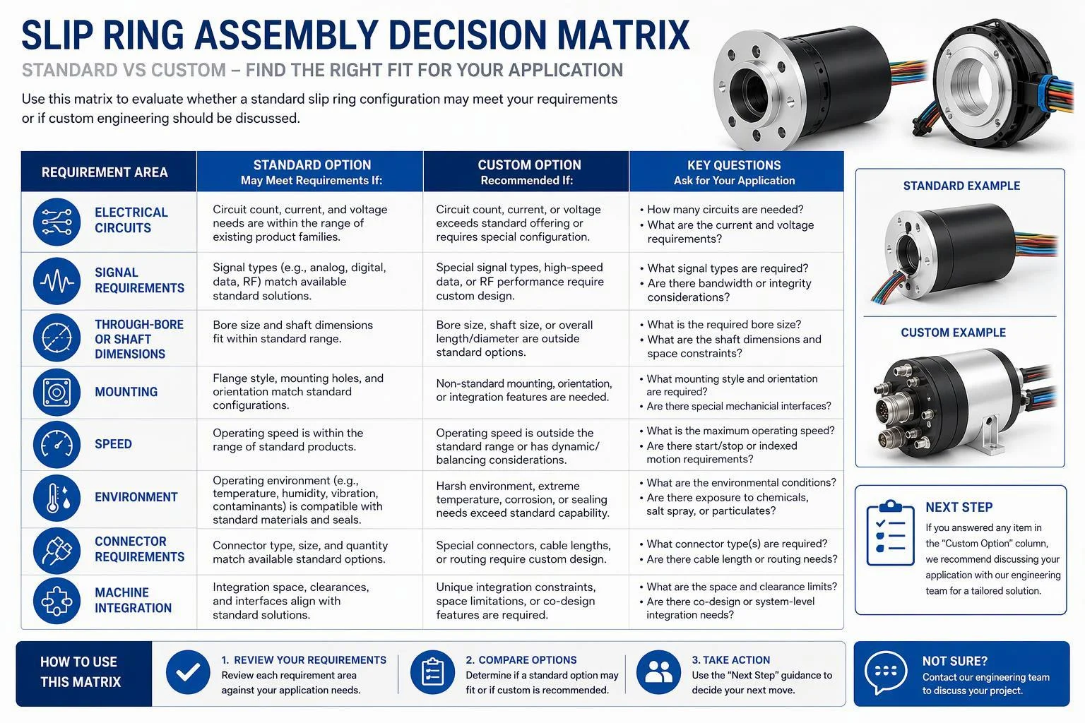
An existing slip ring configuration may be suitable when its circuit arrangement, signal interfaces, dimensions, mounting, rotational duty and environmental conditions match the machine. A custom assembly should be considered when multiple electrical and mechanical requirements cannot be accommodated by an existing configuration, or when the rotating interface must be engineered around the machine.
When a Standard Configuration May Be Suitable
A standard configuration is worth evaluating when the circuit count and current levels match, signal interfaces are available, dimensions and mounting fit, and rotational duty and environment are compatible. Standard is not a compromise; it is often the lower-risk choice.
When Customization May Be Required
Custom engineering becomes relevant with unusual circuit quantities, mixed current levels, multiple voltage groups, high current plus signals or data, special Ethernet or encoder requirements, restricted space, non-standard through-bore or flange interfaces, unusual rotational duty or harsh environments.
Design Inputs for a Custom Assembly
Provide a circuit table, signal requirements, a mechanical drawing, through-bore or shaft dimensions, mounting information, speed and duty cycle, environment, cable and connector requirements, and project quantity and stage. These inputs let the supplier evaluate the complete interface rather than a single rating.
JINPAT Application Discussion
OEM engineers can submit complete electrical and mechanical requirements to JINPAT for an application review covering specification review, product configuration, custom design discussion and quotation.
8. What Should Be Validated Before a Slip Ring Assembly Is Approved?
Validation should confirm the electrical, signal, mechanical, thermal and environmental requirements defined by the OEM. Test methods and acceptance limits should be agreed before design approval whenever possible, so supplier and customer evaluate the same operating conditions and performance expectations.
Electrical Verification
Confirm circuit continuity, circuit identification, grounding, insulation and, where specified, dielectric requirements. Acceptance criteria should come from your own electrical safety requirements or the applicable project standard.
Signal and Communication Verification
Verify encoder functionality, CAN communication and Ethernet or EtherCAT operation, plus signal integrity and EMC performance where required. Testing with representative cables and machine equipment is more informative than a bench check alone.
Thermal Verification
Evaluate temperature rise under representative electrical loading and ambient conditions, with measurement locations and acceptance criteria defined in advance.
Mechanical Verification
Check overall dimensions, mounting interface, through-bore or shaft dimensions, rotational operation, cable routing, connector arrangement and assembly fit against the approved drawing.
Environmental Verification
Confirm ingress, vibration or shock, and corrosion requirements against the agreed criteria.
Documentation and Change Control
Hold approved drawings, circuit diagrams, pinouts, inspection records, and configuration identifiers under change control.
9. What Are the Most Common Slip Ring Assembly Design Mistakes?
Most slip ring assembly problems trace back to requirements defined in isolation. These are the recurring ones.
Selecting the Slip Ring Only by Current and Voltage
Two ratings cannot describe signals, duty, mounting, or thermal conditions.
Ignoring the Rotor and Stator Mechanical Interfaces
Undefined attachment points and torque restraint load the assembly and its cables.
Specifying Maximum RPM Without Duty Cycle
Speed alone omits motion profile, start-stop frequency, and continuous versus oscillating operation.
Adding Data or Encoder Requirements Late in the Design
Late protocol changes can force circuit, shielding, and connector redesign.
Ignoring Grounding, Shielding and EMC
EMC decisions made after the architecture is fixed are expensive to correct.
Providing Dimensions Without a Machine Interface Drawing
Bare dimensions omit alignment, clearance, and mounting context the supplier needs.
Loading the Slip Ring With Unsupported Shaft or Cable Forces
Cables and shafts must not carry loads the assembly was not designed for.
Ignoring Thermal Conditions
Enclosure, ambient heat, and simultaneous loading change the real electrical margin.
Selecting an IP Rating Without Describing the Environment
A rating code does not describe washdown, condensation, or chemical exposure.
Introducing Validation Requirements After Design Approval
Late acceptance criteria reopen designs and delay programs.
Changing Electrical or Mechanical Interfaces Without Reviewing the Complete Assembly
A single interface change can invalidate thermal, EMC, or fit assumptions.
10. What Information Should Be Included in a Slip Ring Assembly RFQ?
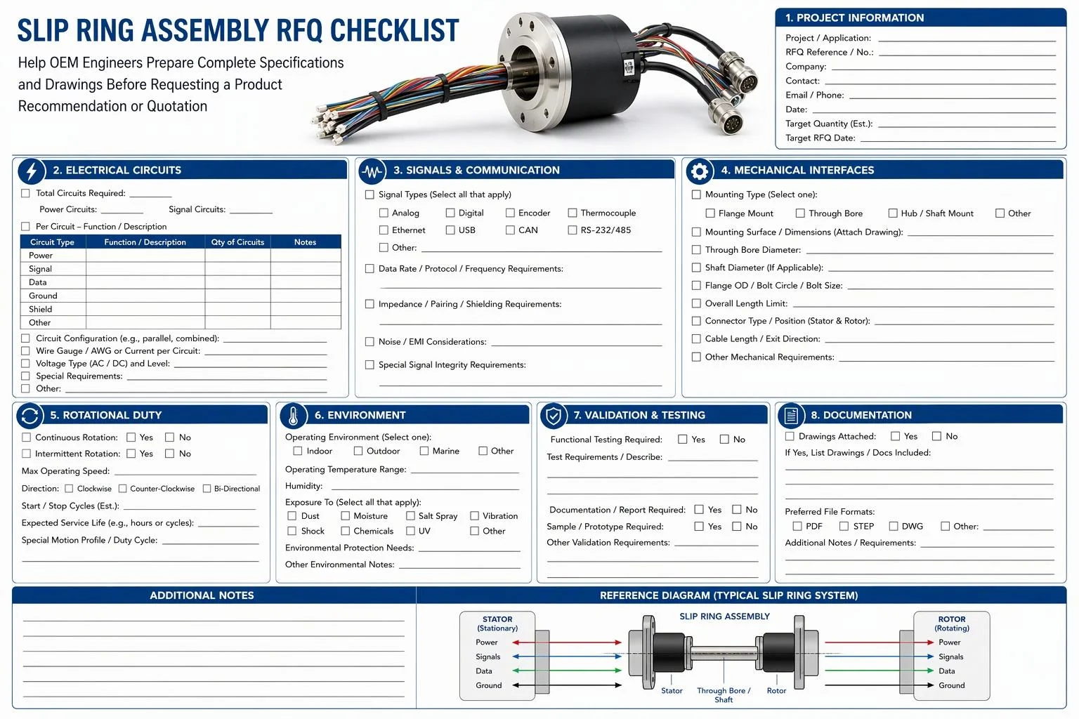
A complete slip ring assembly RFQ combines electrical, signal, mechanical, rotational, environmental, validation, and project information. Detailed requirements and drawings let the supplier evaluate the complete rotating interface and decide whether an existing product or a customized configuration is more appropriate.
Electrical Information
State the number of circuits, current per circuit, continuous and peak current, voltage, AC or DC, simultaneous loading, and grounding and isolation requirements.
Signal and Data Information
List signal types, communication protocols, encoder requirements, channel quantity, shielding, grounding, cable and connector requirements, and any relevant communication performance criteria.
Mechanical Information
Provide through-bore or shaft dimensions, maximum outside diameter and length, rotor and stator interface, mounting method, flange or hole pattern, cable exit direction, connector orientation, and a machine drawing where available.
Operating Conditions
Describe rotational speed, continuous or intermittent operation, duty cycle, start-stop frequency, vibration and shock, ambient temperature, dust and water exposure, and corrosion or chemical exposure.
Validation and Documentation
Specify required testing, acceptance criteria, technical drawings, inspection requirements, required reports, and applicable project documentation.
Project Information
State prototype or production stage, quantity, project schedule, spare-unit strategy where relevant, and the requested engineering review or quotation scope.
11. How Should OEMs Evaluate a Slip Ring Assembly Supplier?
Supplier evaluation should extend beyond product dimensions and headline electrical ratings. OEM engineers should assess whether a supplier can understand the complete rotating interface, review electrical and mechanical requirements together, provide useful documentation, manage customization and design changes, support validation requirements, and maintain configuration consistency through the project lifecycle.
Engineering and Application Review
Ask whether the supplier reviews circuit-level requirements, signal and communication needs, mechanical integration, the rotor and stator interface, environmental conditions, and standard-versus-custom options together.
Technical Documentation
Ask for the drawing set, circuit and pinout information, connector details, installation instructions and configuration records, then check that they match the quotation.
Customization and Change Management
Confirm how electrical, mechanical, cable, connector and mounting changes are raised, reviewed, approved and recorded, and who signs off the design before production.
Validation and Quality Documentation
Agree which inspection records, validation records and test reports you need, and confirm the supplier can supply them against your acceptance criteria.
Lifecycle Support
Check maintenance documentation, spare-unit planning, replacement support and technical communication for the years after the machine ships.
12. Frequently Asked Questions About Slip Ring Assembly Design
These answers address the questions OEM engineers raise most often during slip ring assembly specification.
What Is the Difference Between a Slip Ring and a Slip Ring Assembly?
A slip ring is the rotating electrical transmission function; a slip ring assembly is the complete electrical and mechanical structure that integrates that function into the machine.
What Information Should an OEM Provide Before Selecting a Slip Ring Assembly?
Provide circuits, current per circuit, voltage, signal protocols, mechanical interfaces and dimensions, rotational duty, environment, mounting and validation requirements.
Can Power and Ethernet Be Transmitted Through the Same Slip Ring Assembly?
Combined transmission may be possible depending on the assembly design, but power architecture, Ethernet requirements, segregation, shielding, grounding and signal integrity must be defined before product selection.
When Should an OEM Use a Through-Bore Slip Ring Assembly?
A through-bore configuration suits applications where a shaft, pipe, cable bundle or other machine component must pass through the centre of the rotating electrical interface.
When Should a Custom Slip Ring Assembly Be Considered?
Customization becomes relevant when existing configurations cannot meet the required circuit architecture, signal transmission, dimensions, mounting, rotational duty, environment or machine-specific integration.
What Should Be Tested Before a Slip Ring Assembly Is Approved?
Test electrical continuity and grounding, signal and communication operation, thermal behaviour, mechanical fit and rotation, and environmental performance against agreed acceptance criteria.
Conclusion: Design the Slip Ring Assembly Around the Complete OEM Machine Requirements
Design the slip ring assembly in a fixed sequence: define the electrical and signal architecture, define the rotor and stator mechanical interfaces, evaluate rotational, thermal and environmental conditions, determine standard versus custom, establish validation requirements, then prepare drawings and RFQ information and request an engineering review.
That order matters because each step constrains the next. A circuit table written before the bore and mounting envelope is fixed may not survive the mechanical review, and a validation plan agreed after design approval often tests the wrong conditions. Working in sequence keeps the electrical and mechanical sides of the rotating interface in step, and it gives the supplier a requirement set it can actually evaluate.
A slip ring assembly is a complete rotating electrical and mechanical interface, not a single specification value. Current per circuit, bore, mounting, cable routing, duty cycle, thermal conditions and environment all interact, and the assembly is only correct when they are reviewed together.
To move forward, submit your slip ring assembly requirements and machine drawings to JINPAT for an application review. You can also request a product recommendation or quotation based on your electrical, signal, mechanical, rotational and environmental requirements.

