
Hollow Shaft Slip Ring Bore Size and Mounting Best Practices
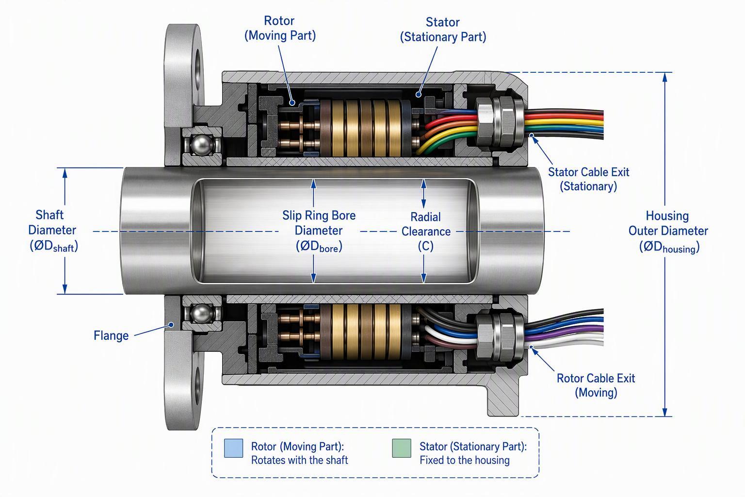
Quick Answer: How Should You Size and Mount a Hollow Shaft Slip Ring?
Hollow shaft slip ring selection should begin with the actual shaft diameter, the installation clearance the assembly method requires, the available radial and axial envelope, the mounting interface and the cable routing. Selecting a bore size from the shaft nominal diameter alone omits the tolerance stack-up, housing outer diameter and restraint arrangement that decide whether the part fits and survives rotation.
Standard LPT through-bore models: bore ID against housing OD. Values are the published standard table for the LPT range; axial length varies with circuit count on the same bore and is not shown here.
Define the shaft diameter before selecting the slip ring bore
Start from the measured shaft at the exact axial position where the slip ring will sit, not from the nominal diameter on the equipment drawing. A shaft may be turned down, sleeved, plated or fitted with a collar over part of its length, and the slip ring bore only ever sees the section it surrounds.
Record three values for that section: the nominal diameter, the actual tolerance limits from the shaft drawing, and the surface condition (ground, turned, coated, sleeved). These three values, not the nominal alone, define the smallest bore the shaft can pass through and the largest bore that still leaves a workable installation.
Allow practical installation clearance instead of matching the bore directly to the shaft
A bore equal to the shaft nominal diameter is a nominal coincidence, not a design decision. The bore must clear the shaft at its upper tolerance limit, pass over any step, keyway burr, coating or sleeve, and still allow the slip ring to be centred before its fasteners are tightened.
JINPAT's through-bore installation guidance is explicit on this sequence: stabilise the slip ring on the rotating shaft, adjust the position of the shaft relative to the mounting hole, and ensure concentricity between shaft and slip ring before fixing the rotor screws. Clearance that is too tight removes the adjustment range that step depends on.
Check the complete mechanical envelope, not only the through-bore diameter
A through-bore slip ring occupies an annulus, and the annulus has an outer diameter, an axial length, a rotor-side collar or hub, an anti-rotation tab and two cable exit regions. Any of these can be the dimension that fails first.
Take the LPT standard range as an illustration of how bore and housing scale together: the LPT025 has a 25.4 mm bore in an 86 mm housing, the LPT050 a 50 mm bore in a 119 mm housing, and the LPT120 a 120 mm bore in a 207 mm housing. A bore decision therefore immediately commits radial space around the shaft, and the axial length grows further with circuit count on the same bore.
Confirm how the rotor and stator will be mechanically constrained
Relative rotation between the two halves must be controlled by the machine structure, not by the slip ring's internal contact system. In the JINPAT LPT arrangement the rotor side is fastened to the shaft through an aluminium collar ring with screws, while the stator side is held by an anti-rotation tab that receives a poke rod in its U slot.
Decide early which half rotates with the shaft, which half is grounded to the frame, and which feature absorbs the reaction torque. If both halves are rigidly tied to structures that are not perfectly aligned, the slip ring becomes a structural member between them.
Key Takeaways for OEM Mechanical Design
Bore diameter must be selected from the real shaft and installation conditions rather than nominal equipment size alone.
The shaft, slip ring bore, outer diameter, axial length, flange, cable exits, and surrounding components must be reviewed as one mechanical envelope.
The slip ring should not be used as the primary bearing or structural support unless the selected design is specifically intended for that function.
Mounting architecture must control relative rotation without introducing excessive misalignment or mechanical load into the slip ring.
Electrical configuration, cable routing, environment, and maintenance access should be checked before the mechanical design is frozen.
A complete mechanical drawing and operating-condition package improves model selection and custom engineering review.
What Dimensions Must You Define Before Selecting the Bore Size?
Bore selection depends on the relationship between the rotating shaft, the assembly clearance the installation method requires, the slip ring outer diameter, the axial space, the mounting features and the nearby components. Each of these is a dimension on the equipment drawing, and any one of them can override the bore that looked correct in isolation.
Shaft diameter and actual dimensional variation
Define the shaft diameter with its tolerance band at the installation station, and note whether the surface is a ground bearing seat, a raw turned surface, a plated section or a sleeve. A tolerance band is what the bore must clear, not a single number.
Required bore diameter and installation clearance
State the minimum bore as the shaft upper limit plus the clearance your assembly method needs. If the slip ring must slide over a step, key, shoulder or coupling flange, the largest obstruction on the insertion path sets the minimum bore, not the shaft itself.
Slip ring outer diameter and available radial envelope
Measure the free radial space from the shaft centreline outward to the nearest obstruction: frame member, guard, bearing housing, hydraulic line or cover. Compare that against the housing outer diameter of candidate models, remembering that the housing diameter is fixed by the product architecture for a given bore and circuit count.
Axial length and available installation depth
The axial length must cover the housing body, the rotor-side collar or hub, the anti-rotation tab and any connector bodies. On the LPT range the same bore appears in several lengths because circuit count changes the stack, so axial space should be treated as a variable tied to the electrical specification.
Cable exit direction and bend space
Rotor-side and stator-side leads leave the housing in defined directions. Reserve space for the exit direction, the first bend and the service loop before the enclosure is closed, and check that the exit does not point into a rotating part.
Flange, mounting holes, and adjacent component clearance
If a flange or mounting plate is used, confirm the bolt pattern, the pilot or spigot location, and the wrench access for each fastener. Screw heads, washers and locking features all consume clearance that is easy to omit from a layout sketch.
How Much Clearance Should You Leave Between the Shaft and Slip Ring Bore?
There is no single universal clearance value for every hollow shaft slip ring installation. The correct clearance is derived from the shaft tolerance limits, the bore limits on the selected slip ring drawing, the assembly method, the alignment capability of the mounting, coating or sleeve thickness, thermal behaviour and service conditions, and the supplier drawing remains the final dimensional reference.
Separate nominal shaft diameter from required bore diameter
The nominal diameter is a label. The required bore is a functional dimension that must clear the shaft at its maximum material condition, pass any intermediate feature, and still allow centring before fastening. Treat the two as separate line items in the design record.
Account for shaft tolerances and dimensional stack-up
ISO 286-1 establishes the ISO code system for tolerances on linear sizes and notes that the precondition for applying a fit is that the nominal sizes of the hole and shaft are identical. It also states that diameter tolerances alone are often insufficient to control the intended function of a fit, and that form, orientation and location deviations, surface texture, material and operating temperature may all need to be considered.
That is directly relevant here: a bore-to-shaft relationship is a fit, and the fit has to be evaluated against the shaft's actual tolerance class and form, not against a nominal number. Stack the shaft tolerance, the bore tolerance, any sleeve or coating, and the alignment error of the mounting before deciding whether the resulting clearance is adequate.
Consider coatings, sleeves, plating, and surface treatments
Hard chrome, nickel plating, thermal spray, paint and pressed-on wear sleeves all add to the effective shaft diameter, and some add unevenly. A bore that clears a bare shaft may not clear the same shaft after surface treatment, so the coated diameter belongs in the calculation.
Consider thermal expansion where operating conditions make it relevant
Where the shaft and housing operate at different temperatures, or where the machine sees significant temperature swings, differential expansion changes the running clearance. Linear thermal expansion is proportional to the original dimension, the temperature change and the material's expansion coefficient, so the effect scales with bore size and is largest on big bores in hot equipment. Evaluate it when the duty involves sustained temperature difference between shaft and slip ring housing.
Check assembly and removal access
Clearance serves two moments: installation and removal. A slip ring that must be pulled off a shaft after years of service needs the same path back out, including space for pullers or a withdrawal sleeve and enough axial room to slide the unit clear of the shaft section it surrounds.
Use the supplier drawing as the final dimensional reference
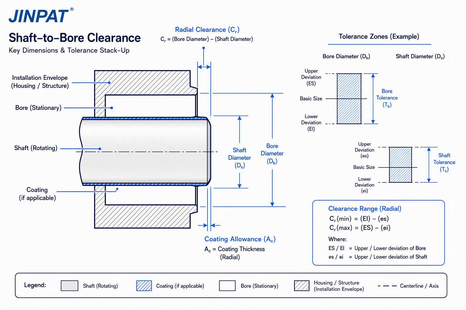
Bore limits, concentricity requirements, fastener sizes and tab geometry are stated on the model outline drawing. Confirm the candidate model's drawing against the measured shaft and envelope, and treat any general guidance as a starting point rather than a substitute for that drawing.
How Should You Evaluate Shaft Alignment, Runout, and Concentricity?
Poor alignment introduces unwanted mechanical loading, vibration, cable movement and uneven operating conditions. Engineers should review the complete rotating assembly, because the slip ring bore is a passage through the unit, not an alignment reference for the machine.
Check shaft runout and concentricity at the installation location
Measure runout and concentricity at the axial position the slip ring will occupy, with the shaft supported as it will be in service. A shaft that is true near its bearings can still run out at an overhung slip ring station, and that error translates directly into relative motion between rotor and stator.
Review radial and axial misalignment sources
Typical sources include frame weldment tolerance, bearing clearance, shaft straightness, mounting plate flatness and the position of the anti-rotation anchor relative to the shaft axis. Each contributes to the total misalignment the slip ring must tolerate, and they add rather than cancel.
Avoid transferring bearing loads into the slip ring
JINPAT's through-bore precautions state that the slip ring cannot bear the weight of its connected equipment, and that wires should be free from extra pull and weight. The same principle applies to radial and axial loads: shaft support belongs to the machine's bearings, and the slip ring should carry only the reaction torque its restraint feature is designed to take.
Separate equipment support functions from signal and power transmission functions
Give the shaft its own bearing arrangement, give the slip ring a defined mounting interface, and give the cables a strain-relieved route. When these three functions are separated, alignment errors show up as small relative movement at the restraint rather than as load through the housing.
Verify the installed assembly before continuous operation
After assembly, rotate the shaft through its working range and observe the slip ring body, the anti-rotation tab and the cable loops. Any visible oscillation of the housing, tab contact at the end of its slot, or cable tightening indicates an alignment or restraint problem to correct before production running.
Which Mounting Architecture Should You Use?
The correct mounting method depends on equipment geometry, how reaction torque is restrained, service access, alignment capability, rotational speed and the mounting interface the selected slip ring model is actually built with. The model drawing defines the interface; the machine design must match it rather than the reverse.
Flange mounting for defined stator positioning
Flange mounting suits arrangements where the stationary side can be bolted to a machined surface with a defined position relative to the shaft axis. Review mounting surface flatness, the pilot or spigot that establishes concentricity, bolt access for assembly and torqueing, and clearance around the flange for the cable exits.
JINPAT's LPT installation sequence places concentricity verification before screw tightening, which only works if the flange or mounting hole allows the housing to be positioned while the fasteners are loose. A flange that pulls the housing off-centre as the bolts are tightened defeats the purpose.
Rotor-side clamping or hub mounting
On the LPT through-bore design the rotor side is secured to the shaft by an aluminium collar ring with screws. This clamps the rotating half to the shaft so it turns with the machine, and it is the interface that must be concentric with the shaft before tightening.
A hub or collar interface should constrain rotation and axial position without crushing or distorting the housing. Where the shaft surface is soft, coated or plated, consider how clamping load is distributed so the collar grips without marking the running surface.
Anti-rotation features for the stator
The stationary half needs controlled restraint, because without it the stator would be dragged around by the rotor. JINPAT's LPT arrangement uses an anti-rotation tab with a U slot that receives a poke rod, and the installation guide notes that wires should be routed to avoid twining with the rotor.
A tab-and-rod restraint transmits torque while permitting the small relative movement that misalignment produces. Making the stator rigid in every direction instead converts that movement into load on the housing and bearings.
Keyed, clamped, or custom interfaces
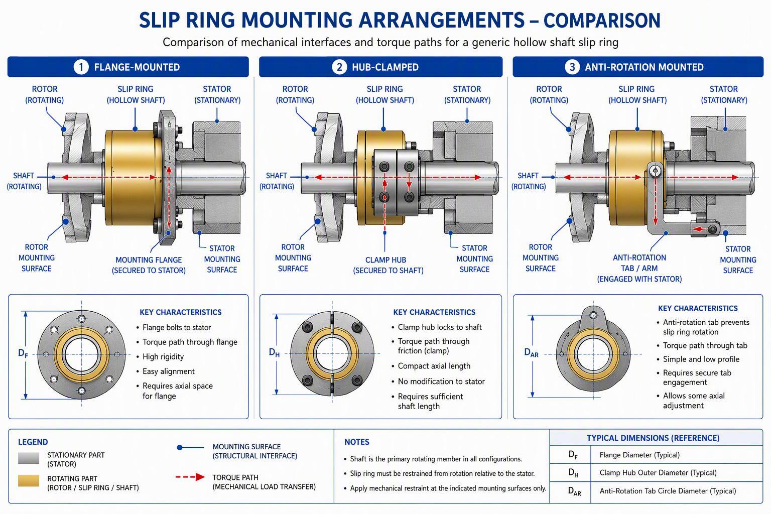
The final interface should follow the actual model drawing and the application requirements. Some designs use a flange, some a collar and tab, some a keyed or pinned connection, and some a fully custom bracket negotiated with the supplier. Assuming one method applies to every hollow shaft slip ring is a common source of late redesign.
Hollow Shaft Slip Ring Mounting Selection Matrix
Design Condition | Mounting Consideration | What to Check | Common Risk |
|---|---|---|---|
Limited axial space | Compact mounting interface | Overall length and service access | Interference during assembly |
Limited radial space | Small outer diameter relative to bore | Housing clearance | Oversized slip ring envelope |
Long rotating shaft | Alignment and runout control | Shaft support and concentricity | Excessive mechanical loading |
Frequent maintenance | Accessible mounting and connectors | Removal path and cable access | Difficult replacement |
High cable density | Controlled cable routing | Bend radius and exit direction | Cable interference or fatigue |
Custom equipment geometry | Custom mounting interface | Drawings and installation constraints | Late-stage mechanical redesign |
The matrix is a screening tool, not a specification. It identifies which constraint is likely to govern the mounting decision, so the engineer knows which dimension to fix first and which supplier drawing to request. Where two rows apply at once, as they often do on retrofit projects, the tighter constraint normally drives the architecture and the other becomes a verification item.
How Do Cable Routing and Connector Locations Affect the Mechanical Design?
Cable routing is part of the mechanical envelope. A slip ring can fit dimensionally and still be unusable if its cable exits foul the shaft, frame, bearings, covers or maintenance access, so exit direction and bend space belong in the layout before the enclosure is frozen.
Define rotor-side and stator-side cable exit directions
The rotor leads turn with the shaft and the stator leads stay with the frame, so the two exit paths diverge immediately. Define the direction of each exit in the installed orientation, and check that neither points into a component that will be added later.
Reserve bend space around cable exits
Leads need room for their first bend and for a service loop that accommodates assembly tolerance. Reserve that volume in the layout, and keep the bend away from sharp edges, fastener heads and rotating surfaces.
Prevent cables from carrying mechanical restraint loads
JINPAT's precautions state that wires should be free from extra pull and weight, and that wire insulation must not be damaged during installation. Strain relief should be provided by the machine structure, not by the slip ring terminals, and the cable should never be the element that limits stator rotation.
Separate rotating and stationary cable paths
The LPT installation guide specifically warns that wires should be arranged to avoid twining with the rotor. Route rotor and stator harnesses on opposite sides of the mounting structure or through separate glands, and verify the separation through the full rotation range rather than at one position.
Plan connector and maintenance access before freezing the enclosure
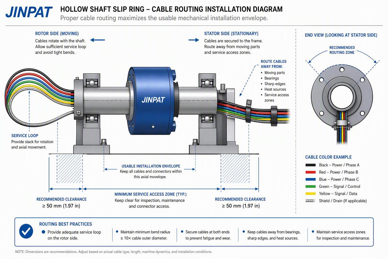
Connectors, terminal blocks and cable glands need hand access and tool access. If a cover must come off to reach them, confirm the cover can be removed with the machine in its service position and that the harness has enough slack to allow it.
What Environmental Conditions Should Be Included in the Installation Design?
The mounting design should consider the real installation environment, because sealing, enclosure design, contamination, moisture, temperature, vibration and maintenance conditions affect both slip ring selection and mechanical integration. Environmental protection added late usually costs envelope space that the layout no longer has.
Define the actual exposure to dust, moisture, oil, coolant, or outdoor conditions
List what the installation will actually see: chips and dust, washdown, coolant mist, oil spray, condensation, salt air, UV or direct weather. Distinguish continuous exposure from occasional exposure, since the enclosure strategy differs.
Confirm the required enclosure or protection level for the final installation
The IP code system is defined by IEC 60529, which classifies degrees of protection provided by enclosures with respect to access to hazardous parts, ingress of solid foreign objects and ingress of water. The standard also notes that it does not by itself address every external influence, listing mechanical impact, corrosion, corrosive solvents, fungus, vermin, solar radiation, icing, condensation and explosive atmospheres as matters for the relevant product standard or separate measures.
That distinction matters for a rotating interface: an IP rating describes the enclosure's tested protection, not the slip ring's resistance to coolant chemistry, vibration or thermal cycling. Confirm the protection level required for the final installation and how it will be achieved, whether by the slip ring's own housing, a machine enclosure, or both.
Consider drainage, ventilation, and sealing strategy where applicable
Where moisture can collect, provide a drain path rather than a sump. Where heat must escape, avoid sealing the housing into an insulated pocket. Sealing and ventilation pull in opposite directions, so decide which the installation needs and design the enclosure around that decision.
Review vibration and shock conditions
Vibration loosens fasteners and fatigues cable strands. Specify the vibration and shock environment in the RFQ, use locking measures on mounting screws, and support the harness at intervals so the slip ring terminals are not the first point of movement.
Confirm operating and storage temperature requirements
State both the operating temperature range at the slip ring location and the storage and transport range, since a machine may sit in an unheated yard before commissioning. Temperature also feeds back into the clearance calculation through differential expansion.
Make sure environmental protection does not block service access or cable routing
A sealed cover that cannot be removed without disconnecting the harness turns a routine inspection into a major intervention. Check that guards, boots and covers can be opened with the cables still connected, and that the protection does not force the cable into a tighter bend than the route allows.
How Do Electrical Requirements Affect Bore Size and Mechanical Envelope?
Electrical requirements can change the physical size of the slip ring. More circuits, higher current, mixed power and signal transmission, connectors, shielding and additional transmission modules may increase outer diameter, axial length or cable space, so the electrical specification and the mechanical envelope have to be developed together.
Axial length of the LPT050 (50 mm bore, 119 mm OD) at 6, 12, 18 and 24 circuits, from the published outline drawing table. Length grows with circuit count on an unchanged bore; values are model-specific and not a rule for other bores.
Define power circuits, signal circuits, and communication requirements
List circuit count, current per circuit, voltage, and the signal types carried. JINPAT's standard LPT range, for example, is published with 6 to 24 circuits and 5 A signal, 10 A or 15 A power options depending on bore size, with standard support for serial communication, RTD, thermocouple, sensor and encoder signals. Other signal types are handled as separate engineering discussions rather than assumed.
Separate bore requirements from electrical circuit requirements
The bore is set by the shaft and the routing through the centre; the circuit stack is set by the electrical load. They are independent inputs that meet in the product architecture. Deciding the bore first and then adding circuits is fine; assuming the bore determines the electrical capability is not.
Understand why more channels can increase the overall housing size
Each circuit needs ring and brush space along the axis. On the LPT range, the same bore appears in several axial lengths corresponding to 6, 12, 18 or 24 circuits, so circuit count translates directly into length. Higher current per circuit can also change contact and conductor geometry.
Consider mixed power and signal routing during mechanical integration
Power and signal leads may need physical separation and different bend radii. Plan the harness so power conductors and sensitive signal pairs do not share a tight bundle around the rotating interface, and reserve space for shielding terminations where required.
Confirm whether additional transmission functions require an integrated solution
Where the rotating interface must also pass fibre optics, high-frequency signals, or pneumatic and hydraulic media, the centre bore may be used for fluid lines or the unit may need an integrated module. JINPAT's through-bore range is described as accommodating shafts, pneumatic or hydraulic lines, and integrated high-frequency, fibre, encoder, waveguide and fluid joints, but the specific combination must be confirmed against the application rather than assumed.
When Is a Standard Hollow Shaft Slip Ring Enough, and When Is Customization Needed?
A standard model is appropriate when the required bore, mechanical envelope, circuit configuration, speed, environment and mounting arrangement all fall within an existing product configuration. Custom engineering becomes relevant when several mechanical or electrical constraints cannot be satisfied simultaneously by any catalogue configuration.
Choose a standard model when the mechanical and electrical requirements align
The standard route is usually faster and lower risk. If the shaft fits an existing bore, the housing fits the radial envelope, the axial length fits the available depth, the circuit count and current are covered, and the environment is within the published range, a catalogue model is the sensible starting point. JINPAT's LPT range, for instance, covers bores from 12.7 mm to 180 mm in the standard table, with published outer diameters, lengths, voltages, currents and speeds for each.
Consider customization when bore size and outer diameter create packaging conflicts
When the shaft demands a large bore but the radial space forbids the corresponding housing diameter, the standard progression from bore to outer diameter no longer works. This is a genuine packaging conflict and a legitimate reason to discuss a custom architecture.
Consider customization when circuit count or transmission functions change the envelope
Very high circuit counts, high current combined with dense signal content, or added fibre, RF or fluid channels can push the unit beyond a standard length or diameter. JINPAT's published capability for custom work includes through-bore size, circuit configuration, current capacity, environmental protection and installation requirements, which is the set of variables to bring to that discussion.
Consider customization when mounting or cable exits must match existing equipment
Retrofit and platform-derivative projects often have a fixed bolt pattern, a fixed anti-rotation anchor and a fixed cable exit direction. Where the standard interface cannot be adapted with a bracket, a custom interface may be the cleaner solution.
Consider customization when the installation environment requires additional engineering review
Aggressive vibration, corrosive atmosphere, wide temperature swings or a protection level beyond the standard housing all warrant an engineering review before a model is chosen. Bring the environmental data, not just the headline requirement.
Common Mechanical Design Mistakes
Most avoidable integration problems occur when engineers select the slip ring from one dimension or one electrical requirement instead of reviewing the complete rotating interface. The mistakes below are the recurring ones, and each is cheaper to fix on the drawing than on the assembly line.
Selecting the bore directly from nominal shaft diameter
Matching bore to nominal diameter ignores tolerance, coating and insertion path. The result is either a bore that will not pass the shaft at its upper limit or one that leaves no room to centre the unit before fastening.
Ignoring the slip ring outer diameter
A bore that fits says nothing about the housing. Radial space must be checked from the shaft centreline to the nearest obstruction, including the collar, tab and connectors.
Forgetting axial installation and removal space
The unit must slide on and, eventually, slide off. Axial space for the insertion stroke and for withdrawal tooling is routinely omitted from layouts that only show the installed position.
Using the slip ring as a structural bearing support
JINPAT's precautions state plainly that the slip ring cannot bear the weight of its connected equipment. Using the housing to support or centre a shaft loads the contact system and the restraint feature in ways they were not designed for.
Constraining both rotor and stator incorrectly
Over-constraining the stator converts misalignment into load; under-constraining it lets the stator rotate. The restraint should take reaction torque while permitting the small relative movement the installation produces.
Ignoring cable bend space and connector access
A harness that is pinched at the exit, or a connector that cannot be reached with a tool, turns a working design into a maintenance problem. Route and access belong in the layout review.
Freezing the mechanical drawing before confirming the electrical configuration
Circuit count changes axial length on the same bore. Releasing the mechanical drawing before the electrical specification is settled invites a late envelope change.
Assuming one mounting method applies to every hollow shaft slip ring
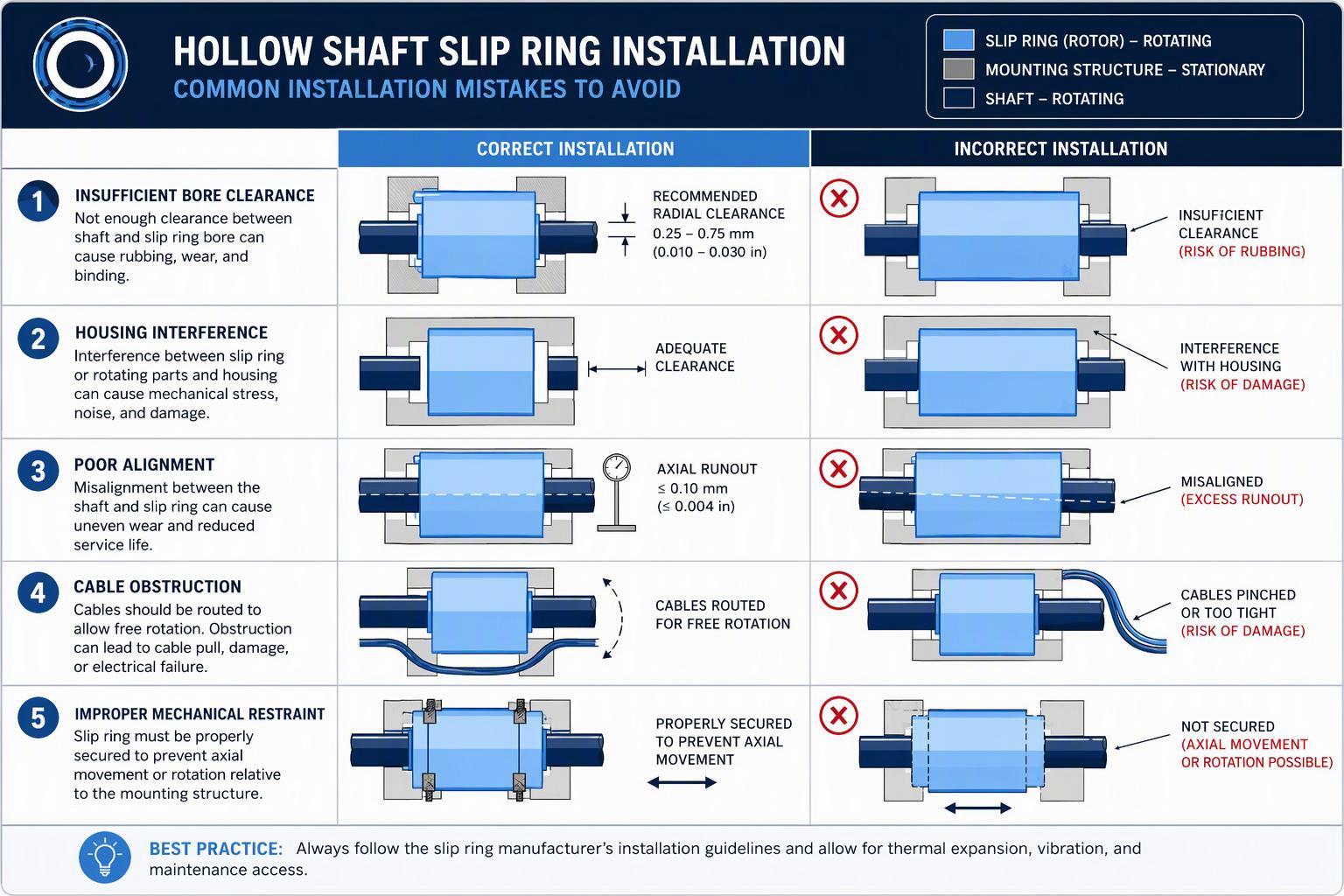
Flange, collar-and-tab, keyed and custom interfaces all exist because different machines need different restraint. Follow the drawing of the model actually selected.
OEM Drawing Checklist for Hollow Shaft Slip Ring Integration
The RFQ or engineering drawing should define both the mechanical interface and the operating requirements, so the slip ring can be evaluated against the actual equipment rather than a single bore dimension. A drawing that shows only the shaft diameter leaves the supplier guessing about the constraints that decide feasibility.
Mechanical dimensions
Shaft diameter
Required through-bore diameter
Available outer diameter
Available axial length
Mounting surface
Flange or anti-rotation requirements
Cable exit direction
Connector clearance
Surrounding component locations
Operating conditions
Rotational speed
Continuous or intermittent operation
Environmental exposure
Temperature requirements
Vibration or shock conditions
Maintenance access requirements
Electrical and signal requirements
Number of circuits
Current requirements
Voltage requirements
Signal types
Communication interfaces
Shielding requirements
Integrated transmission requirements
Attach the equipment drawing or a dimensioned installation sketch to the checklist. A marked-up section view showing the shaft, the free envelope and the intended restraint is worth more than a page of prose, because it lets the supplier check the candidate model against the same geometry the machine will present.
RFQ Checklist: What Should You Send to the Slip Ring Supplier?
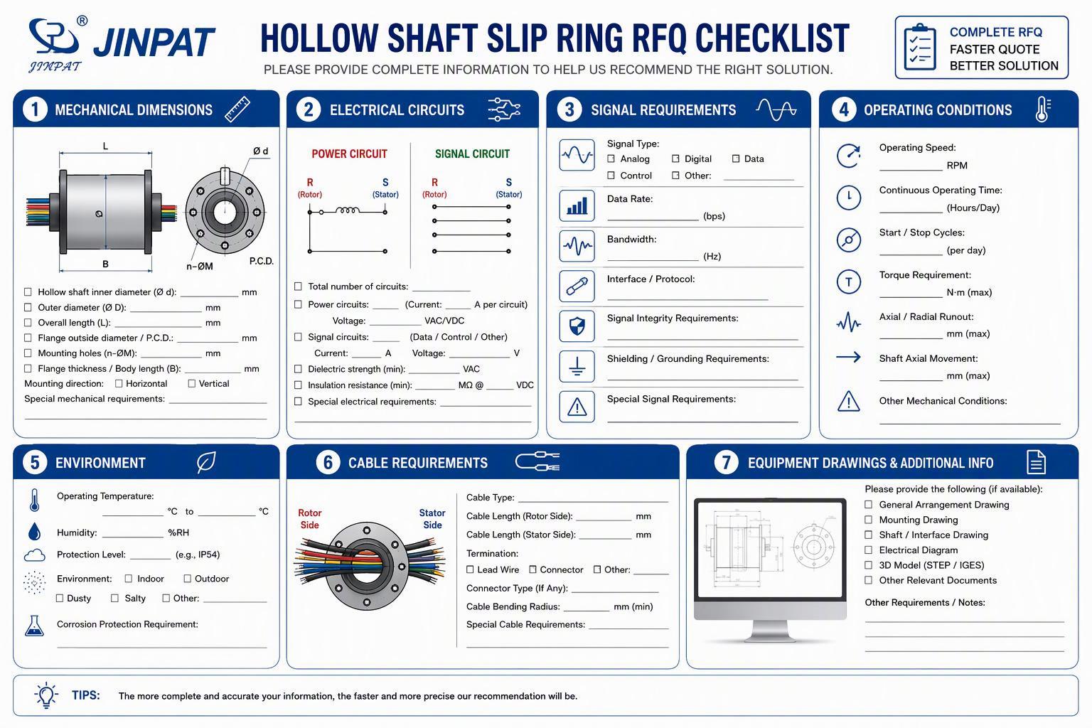
A complete RFQ should include the equipment drawing, shaft and bore requirements, available installation envelope, mounting method, electrical configuration, rotational conditions, environmental requirements and any special interfaces. Supplying all of it at once shortens the review cycle and reduces the risk of a recommendation built on assumptions.
Shaft diameter
Minimum required through-bore
Maximum allowable outer diameter
Maximum allowable axial length
Preferred mounting method
Rotor and stator restraint concept
Required circuit count
Current and voltage per circuit
Signal and communication requirements
Rotational speed
Operating environment
Cable and connector requirements
Equipment drawing or installation sketch
Quantity and project stage
Two items on this list are frequently omitted and both change the answer: the rotor and stator restraint concept, and the quantity and project stage. The first determines whether a standard interface can be adapted; the second determines whether a catalogue model or a custom development is the appropriate commercial route.
How Should You Validate the Installation Before Release?
Final validation should confirm mechanical clearance, alignment, free rotation, cable routing, mounting restraint, electrical continuity and the actual operating conditions before the equipment design is released. Validation is a check against the approved drawing, not a demonstration that the assembly turns.
Verify installed clearances and mechanical interference
Check the running clearance between the housing and every adjacent component through a full rotation, and confirm the bore clears the shaft over the whole installed length rather than at one section.
Check rotor and stator restraint
Confirm the rotor collar is tight and concentric, the anti-rotation tab engages its rod or slot with the intended free play, and locking measures are fitted so vibration cannot loosen the fasteners.
Rotate the assembly through the required motion range
Turn the machine through its full working range, including any indexing or reversal, and watch the slip ring body and restraint for oscillation, contact at the end of travel or audible change.
Inspect cables and connectors during rotation
Observe the rotor and stator harnesses while rotating: no tightening, no rubbing on rotating parts, no sharp bend at the exit, and no load transmitted through the terminals.
Confirm the installed configuration matches the approved drawing
The model, bore, circuit count, cable exit direction and mounting hardware should match the released drawing. Any deviation found at this stage should be corrected or formally recorded.
Record the final slip ring configuration for maintenance and replacement
Record the model designation, bore, circuit configuration, cable lengths and restraint arrangement in the machine documentation. Future replacement then depends on a record rather than on reverse-engineering a unit that may have been superseded.
FAQ
Should the slip ring bore be the same size as the shaft?
No. The bore must clear the shaft at its upper tolerance limit, pass any step, key, coating or sleeve on the insertion path, and still allow the unit to be centred before fastening. The selected product drawing, not nominal equality, defines the acceptable bore.
Can a hollow shaft slip ring support the rotating shaft mechanically?
No, not unless the selected design explicitly specifies that function. JINPAT's through-bore precautions state that the slip ring cannot bear the weight of its connected equipment. Shaft support belongs to the machine's bearings; the slip ring transmits power and signals and takes only the reaction torque its restraint is designed for.
Is a larger bore always better?
No. A larger bore buys insertion margin and routing space through the centre, but it usually brings a larger housing outer diameter and more axial length. The right bore is the smallest one that satisfies the shaft, the clearance and the centre-routing requirement within the available envelope.
Does increasing the bore size increase the slip ring outer diameter?
Generally yes within a product family, but the housing size is not set by bore alone. Circuit count, current rating and product architecture also drive outer diameter and length, which is why the same bore can appear in several housing variants.
What information is needed to select a hollow shaft slip ring?
The essential inputs are the measured shaft diameter with tolerance, the minimum through-bore, the maximum allowable outer diameter and axial length, the mounting and restraint concept, circuit count with current and voltage per circuit, signal types, rotational speed, environment, and cable or connector requirements. An equipment drawing or installation sketch ties them together.
Can the mounting flange or cable exit be customized?
Customization of installation requirements, including mounting and cable exit arrangements, is within the scope JINPAT lists for project-specific work. Whether a specific flange or exit direction is feasible depends on the model and application, so it should be confirmed through an engineering review of the drawing rather than assumed.
When should an OEM request a custom hollow shaft slip ring?
Request a custom review when the bore and the available radial space conflict, when circuit count or added transmission functions push beyond standard lengths, when the existing equipment imposes a fixed mounting or cable exit geometry, or when the environment falls outside a suitable standard configuration. Bring the drawing and the operating conditions to that discussion.
Next Step: Prepare Your Hollow Shaft Slip Ring Requirements
Define the shaft and bore relationship from measured dimensions and tolerance, confirm the complete mechanical envelope including housing diameter, axial length and cable exits, choose the mounting and restraint concept, specify the electrical and environmental requirements, and prepare an equipment drawing before final model selection.
For an application-specific recommendation, submit your shaft dimensions, available installation space, circuit requirements, rotational conditions, environmental requirements and an equipment drawing for engineering review. A dimensioned section view showing the shaft, the free envelope and the intended restraint lets the review check a candidate model against the geometry the machine will actually present.
Discuss your hollow shaft slip ring requirements with a JINPAT engineer or request a quotation based on your operating conditions.

