
High Current Slip Ring Selection Guide for OEM Engineers
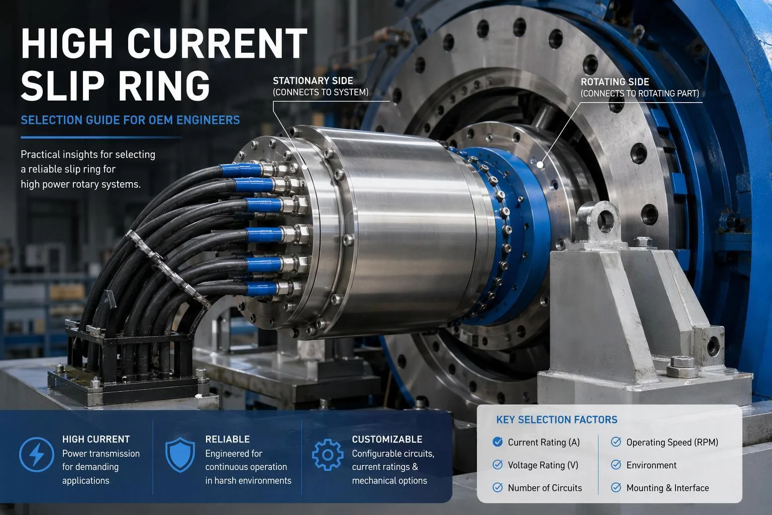
Quick Answer: How Should OEM Engineers Select a High Current Slip Ring?
High current slip ring selection begins with the real electrical load profile: current per circuit, continuous versus peak and inrush current, voltage, simultaneous loading, duty cycle, and thermal conditions. OEM engineers should then evaluate circuit architecture, rotational duty, mechanical integration, environment, mixed signal requirements, validation needs, and whether a standard or custom configuration fits.
Key Takeaways
A high current slip ring cannot be selected from a total current rating alone.
Define continuous, peak, and inrush current by circuit or circuit group, with duration and repetition.
Evaluate thermal performance together with electrical loading and ambient conditions.
Define voltage, circuit count, grounding, isolation, and protection requirements.
Include rotational speed, duty cycle, mounting, space, and environmental conditions.
Evaluate power and signal segregation when power, data, or control channels share one assembly.
Decide whether an existing configuration fits or whether customization should be discussed.
Prepare a complete engineering specification before requesting a recommendation or quotation.
1. What Makes a Slip Ring a High Current Application?
A high current application is defined by the electrical and thermal demands placed on the rotating interface, not by one universal current threshold. Engineers should evaluate current per circuit, load duration, simultaneous loading, peak conditions, conductor and contact design, ambient temperature, enclosure conditions, and required thermal margin before classifying or specifying the application.
Current Per Circuit Matters More Than Total Current Alone
Two assemblies can share the same headline rating and behave very differently. What matters is how the current is spread: how many high-current circuits exist, what current each one carries, whether the assembly mixes different current levels, and whether those circuits are energized at the same time. A single 400 A circuit and four 100 A circuits are not interchangeable requirements, because the second case concentrates heat in four separate contact and conductor paths that may all be loaded at once. Document current per circuit, and mark which circuits run simultaneously.
Continuous, Intermittent, Peak, and Inrush Loads
Continuous current is the steady load the interface carries for long periods. Intermittent current is a heavier load applied for a defined portion of the machine cycle. Peak current is a temporary excursion above normal operation, and inrush current is the short surge at motor starting, transformer energization, or capacitive charging. These conditions stress the interface differently, so describe each one with its magnitude, duration, repetition, and duty cycle rather than collapsing them into one maximum figure.
Why the Real Load Profile Matters
Identical nominal current values can produce different thermal conditions depending on operating profile. A machine that runs one heavily loaded circuit for eight hours continuously heats the interface very differently from a machine that applies the same current for a few seconds per cycle with long recovery intervals. Supply the actual operating conditions — normal load, startup events, sequence, and worst case — instead of only a maximum number, so the thermal review reflects the real duty.
2. What Electrical Requirements Must Be Defined First?
An OEM should define the complete electrical architecture before selecting a high current slip ring. The specification should identify circuit quantity, voltage, current per circuit, AC or DC operation, load characteristics, grounding, isolation, simultaneous loading, and any special protection requirements so the supplier can evaluate the complete rotating electrical interface.
Circuit Count and Current Distribution
List every power circuit with its assigned current, then group circuits that share a load or a protection device. Include protective earth or grounding circuits as separate line items, and state whether spare circuits are required by the machine design. Groups with different loads should be listed separately, because a group of lightly loaded circuits and one heavily loaded circuit place different demands on the assembly.
Voltage and Electrical Architecture
State the operating voltage, whether the supply is AC or DC, and whether one assembly must carry multiple voltage levels. Where several voltage groups share a housing, define the isolation required between them and the separation required between power and signal circuits. These inputs drive internal spacing, insulation, and routing decisions that cannot be recovered later by changing a terminal.
Load Characteristics
Describe what each circuit actually feeds. Resistive loads draw a predictable current; inductive and capacitive loads, motors, and regenerative or changing loads do not. Motor starting conditions and intermittent heavy loads are especially important because they determine the peak and inrush values the interface must survive. Naming the load type lets the supplier interpret the current figures rather than guess at them.
Protection and Coordination Requirements
State the protection strategy the machine already uses: overcurrent and short-circuit protection, the upstream protective devices, and the machine-level electrical safety requirements the assembly must fit into. The slip ring is one element in that coordinated system, so its role should be defined by the project rather than assumed. Fault-current withstand values and short-circuit ratings should come from the project specification, not from a generic figure.
3. How Should Continuous, Peak, and Inrush Current Be Specified?
Continuous, peak, and inrush current describe different electrical stresses and should not be treated as interchangeable. OEM engineers should record the magnitude, duration, repetition, and affected circuits for each non-continuous load, because that record lets a supplier evaluate both electrical capacity and the resulting thermal duty of a high current slip ring.
Continuous Current
Continuous current is the normal operating current, and it should be stated with the duration of continuous loading and the number of circuits loaded at the same time. A figure given without those two companions is ambiguous: the same amperes carried by one circuit for minutes and by six circuits for hours describe two different thermal duties.
Peak or Temporary Current
For peak or temporary current, record the peak magnitude, how long the peak lasts, how often it repeats, and which circuits it affects. A peak that occurs once per shift and a peak that occurs several times per minute both matter, but they do not load the interface in the same way. Repetition frequency is the detail most often omitted and most often needed.
Inrush Current
Inrush current arises from motor starting, transformer energization, capacitive charging, and other short-duration events. Identify which circuits experience inrush, the expected magnitude, and how briefly it lasts. Inrush is short, but it can be far above the continuous value, so it belongs in the specification as a distinct condition rather than folded into the running current.
How to Document the Load Profile
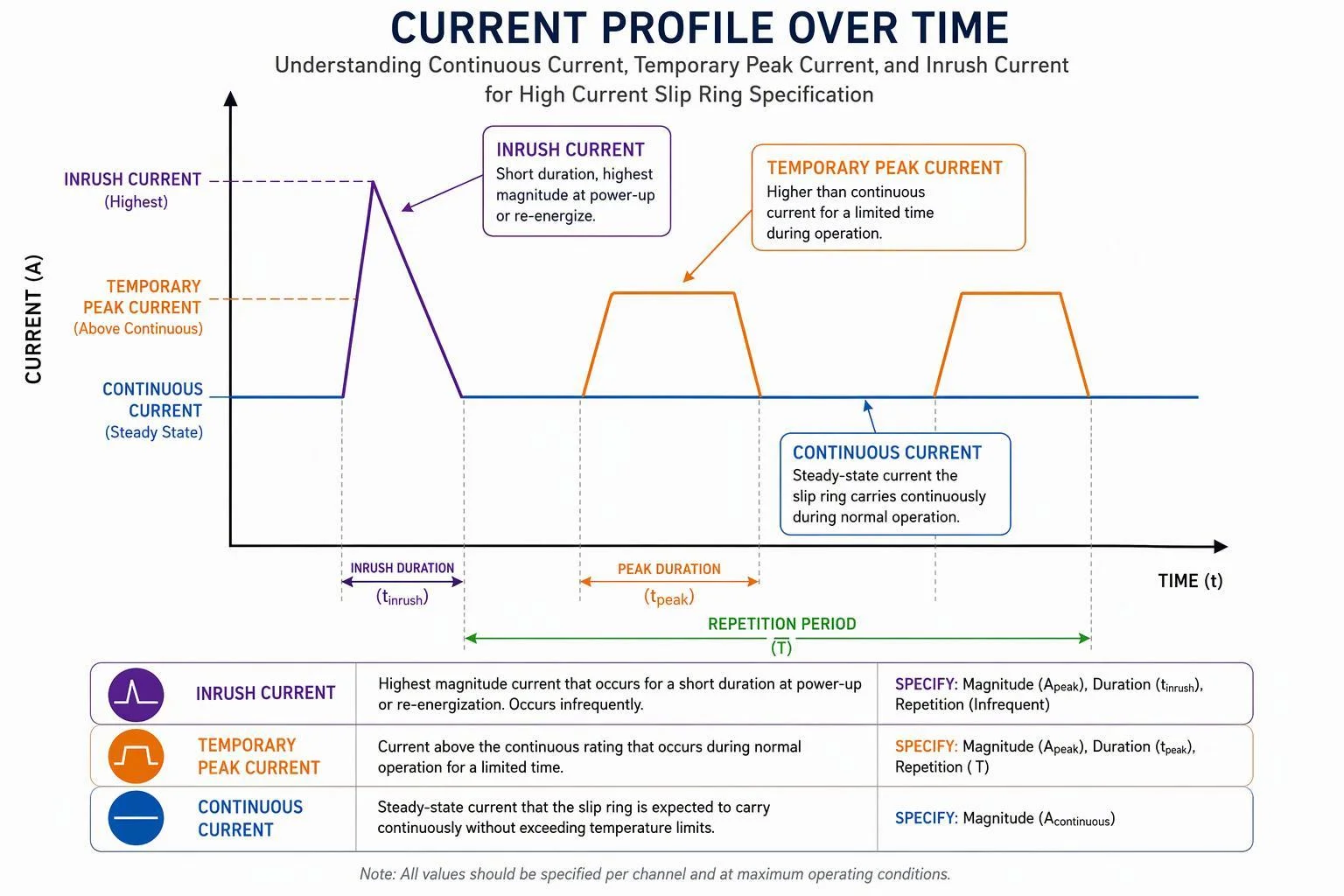
A circuit-by-circuit table is the clearest format: one row per circuit, with current, voltage, load type, continuous and peak values, duration, repetition, and whether the circuit is energized simultaneously with others. Add the operating sequence and a time-based description where the machine cycle is complex, and mark typical and worst-case conditions separately so the review covers both.
4. How Does Thermal Performance Affect High Current Slip Ring Selection?
Current carrying capacity and thermal performance must be evaluated together. Electrical losses, contact resistance, conductor resistance, simultaneous circuit loading, ambient temperature, enclosure design, airflow, rotational duty, and nearby heat sources can all influence temperature rise. Engineers should therefore provide realistic electrical and environmental conditions rather than relying on a current rating alone.
Sources of Heat Inside the Rotating Interface
Heat inside the rotating interface comes from resistance along the current path: conductor resistance, contact resistance at the brush and ring interface, and connection resistance at terminals and joints. Simultaneous loading adds these losses together, because several loaded circuits release heat into the same enclosed volume. The internal electrical losses, not the external load alone, set the temperature the assembly must tolerate.
External Thermal Conditions
The same assembly behaves differently in a ventilated cabinet and a sealed housing beside a motor. Ambient temperature, enclosed installation, nearby heat sources, restricted ventilation, and outdoor solar loading all change how readily internally generated heat leaves the assembly. Describe the installation, not just the air temperature, so the thermal review accounts for how heat is removed.
Temperature Rise and Thermal Margin
Thermal margin is the difference between the temperature the assembly reaches under real conditions and the temperature its components, cables, and insulation can accept. Those limits come from the project: customer-defined temperature limits, component limits, cable and insulation considerations, and the surrounding enclosure and equipment. Define the limits and the measurement points rather than assuming a universal temperature-rise figure applies.
Derating Considerations
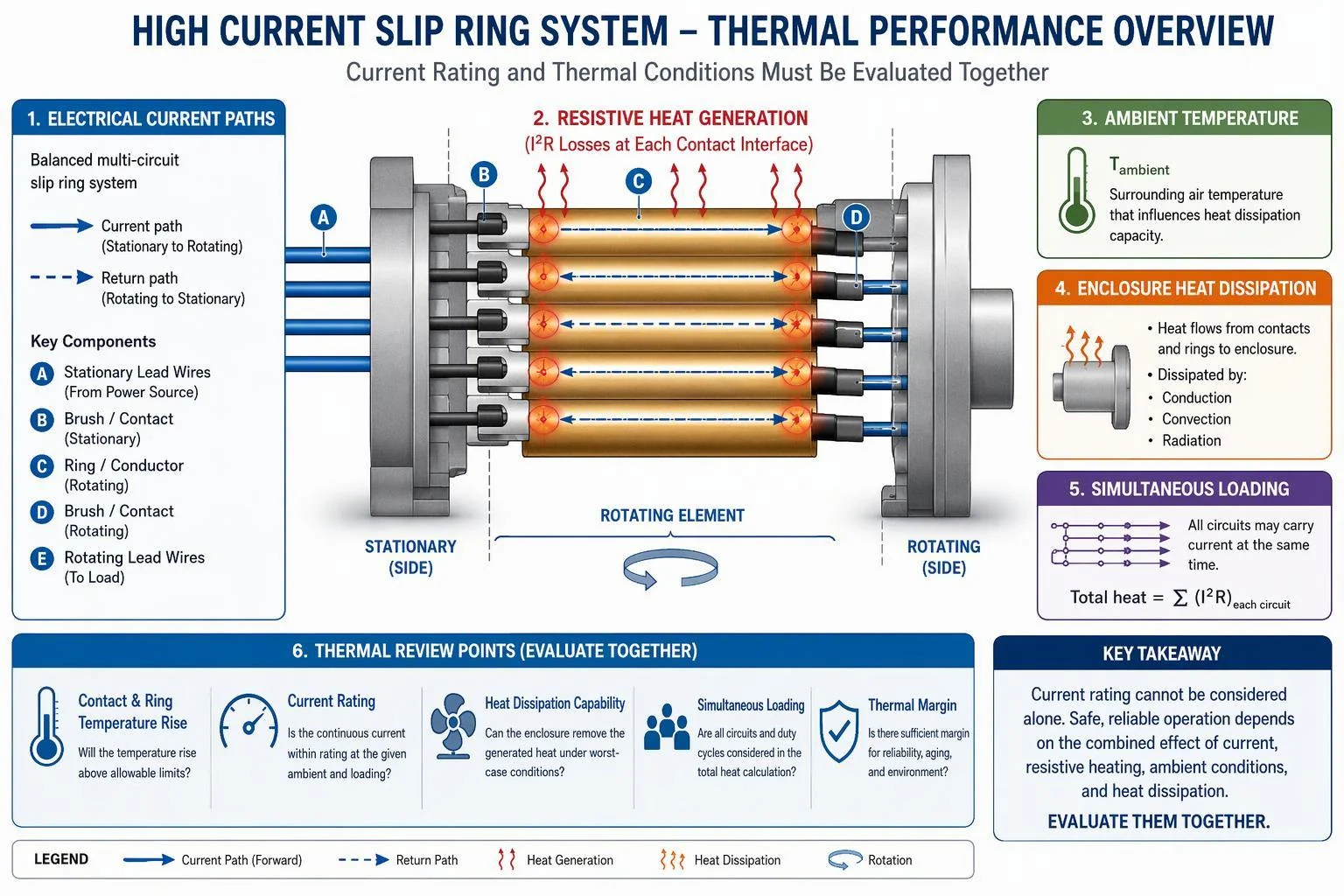
Derating is an engineering review, not a fixed percentage. Elevated ambient temperature, multiple heavily loaded circuits, restricted heat dissipation, and a high duty cycle each reduce the margin available, and they interact. The review should combine the actual load profile with the actual installation conditions and produce a configuration with adequate margin — which is why a nominal rating should not be assumed to hold unchanged in every installation.
5. How Should Circuit Architecture and Current Paths Be Designed?
High current slip ring architecture depends on how the required current is distributed through the rotating interface. Engineers should define circuit count, independent circuits, parallel paths where applicable, current-sharing expectations, connection method, grounding, and physical segregation so the proposed design can be evaluated as a complete electrical system.
Independent High Current Circuits
Independent circuits keep separate electrical functions separate: different current requirements, independent protection, and their own connections and cable routing. Keeping them distinct simplifies fault finding and lets each function be protected on its own terms. Where the machine design calls for spares, list them as independent circuits too, so the architecture is sized for the final machine rather than the first prototype.
Parallel Current Paths
Multiple conductive paths may be considered when a single path is impractical, but parallel paths do not divide current perfectly. Current divides according to each path's resistance and, in AC systems, its impedance; differences in path length, material, joints, and connection quality shift the share. Unequal sharing also creates thermal interaction, because the more heavily loaded path runs hotter. State your current-sharing expectations and let the design be evaluated rather than assumed.
Conductive and Contact Materials
Material choice affects conductivity, contact performance, wear, temperature, and environmental suitability, and these effects trade against each other. No single material is universally best; the right choice depends on current, duty, environment, and service expectations. Plating systems, thickness, and mating-interface design matter as much as the base material, so specify the requirement rather than naming a preferred metal.
Connection Interfaces
Define how power enters and leaves the assembly: cable size requirements, terminals, connectors, and busbar or other high-current interfaces where relevant. Cable exit direction, strain relief, and available space for bending affect both installation and long-term reliability, because loads carried by an unsupported cable can reach the termination. Describe the connection hardware the machine will use, not only the current it carries.
6. How Should High Current Power Be Combined With Signals and Data?
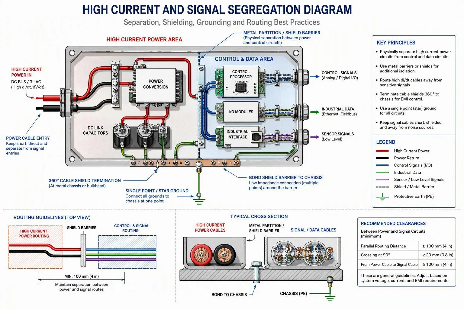
High current power circuits can share one rotating assembly with control, sensor, or data channels, but the complete architecture must address circuit separation, shielding, grounding, routing, and signal integrity. OEM engineers should specify each signal type and communication protocol rather than assume that any data channel can be added to a high current slip ring without additional design review.
Power and Signal Segregation
Physical separation and circuit grouping keep high current conductors away from sensitive channels. Shielding, a defined grounding scheme, and controlled cable routing reduce coupling between power and signal paths; EMC guidance consistently treats grounding topology and cable routing as primary coupling routes, so both belong in the specification rather than in the supplier's assumptions.
Control and Sensor Signals
List analog signals, digital signals, encoder channels, and any machine-specific signals with their voltage levels, channel counts, and sensitivity. Encoder feedback in particular carries position data the drive depends on, so its routing and shielding requirements should be stated explicitly instead of being grouped under a generic "signal" count.
Industrial Communication
Name the protocol — CAN, RS-485, Industrial Ethernet, or another bus — and state its performance requirements. Protocol physical layers impose their own constraints: CAN and RS-485 guidance addresses termination, grounding practice, and isolation to avoid ground loops, so "data" alone is not a usable specification input.
When Fiber Optic Transmission May Be Considered
Fiber optic rotary joints suit high-bandwidth links and provide inherent electrical isolation across the rotating interface, and they can be integrated with electrical channels in one assembly. Specify the optical channel count, fiber type, wavelength, and link budget you require; do not assume a performance level without supplier documentation.
7. What Mechanical Requirements Affect High Current Slip Ring Selection?
Electrical performance cannot be evaluated independently of mechanical integration. OEM engineers should define rotational speed, motion profile, duty cycle, installation envelope, mounting method, shaft or bore requirements, cable routing, service access, and surrounding machine geometry before finalizing a high current slip ring configuration.
Rotational Speed and Motion Profile
State operating speed, maximum speed where relevant, continuous or intermittent rotation, oscillating motion, start-stop frequency, and duty cycle. Speed alone is incomplete: a low-speed slewing application and a continuously rotating one place different demands on the same electrical design.
Installation Envelope
Define maximum outside diameter, maximum overall length, through-bore or shaft requirement, and clearance around the assembly. A high current design needs room for its conductors and contacts, so an envelope that fits a signal-only unit may not accommodate the power section.
Mounting and Mechanical Interface
Identify the flange, shaft, or housing interface, which side rotates and which stays fixed, and the mounting-hole pattern. Supply an interface drawing; dimensions without mounting information leave the supplier guessing about orientation and load paths.
Cable and Connection Routing
Specify high current cable size, cable exit direction, available routing space, connector or terminal access, and service access. Heavy power cables are stiff and need bend radius and strain relief planned at the machine level, not resolved after delivery.
8. What Environmental Conditions Should Be Included in the Specification?
Environmental conditions influence enclosure design, materials, sealing, corrosion protection, thermal performance, cable interfaces, and maintenance. Engineers should describe the actual operating environment — temperature, dust, water, chemicals, vibration, corrosion, and installation location — instead of selecting an IP rating without explaining the exposure.
Temperature and Installation Environment
Give minimum and maximum project temperatures, indoor or outdoor installation, nearby heat sources, and whether the unit sits in an enclosed equipment space. These inputs feed directly into the thermal review in Section 4.
Dust and Water Exposure
Describe dust level, water spray, washdown, and rain or outdoor exposure, and state the required IP rating when the project defines one. The exposure description lets the supplier choose sealing and materials; the rating alone does not.
Corrosion and Chemical Exposure
Note salt, marine atmosphere, oils, hydraulic fluids, cleaning chemicals, and general industrial atmosphere. Corrosive exposure affects housing finish, contact materials, and seal selection, and it should be stated even when no formal rating applies.
Vibration and Shock
Describe machine vibration, mechanical shock, mounting stiffness, and any customer-defined validation requirements. Vibration reaches the contact interface through the housing and cables, so mounting arrangement and cable support belong in the same discussion.
Special Environments
Marine, lifting machinery, heavy industrial equipment, energy equipment, and hazardous-area applications may carry additional requirements. State any certification obligation your project imposes; do not assume a certification requirement or its scope without project information.
9. Standard or Custom High Current Slip Ring: Which Should You Choose?
A standard configuration may be appropriate when its circuit arrangement, current capability, dimensions, speed, mounting, environment, and interfaces match the application. A custom engineering discussion becomes more relevant when the OEM has unusual current distribution, mixed power and data, restricted space, special interfaces, environmental requirements, or machine-specific integration constraints.
When a Standard Configuration May Be Appropriate
A standard high current slip ring is worth pursuing when the circuit architecture, electrical requirements, mechanical envelope, mounting, environment, and required interfaces all fit an existing configuration. Each condition must hold; one mismatch is enough to reopen the comparison.
When Customization May Be Required
Customization becomes relevant with unusual high-current distribution, multiple voltage levels, high current plus signals or data, restricted installation space, a special through-bore, non-standard terminals or cable exits, application-specific mounting, or special environmental requirements. Custom is not automatically better — it is justified by a specific requirement the standard range cannot meet.
Information Needed for a Custom Engineering Review
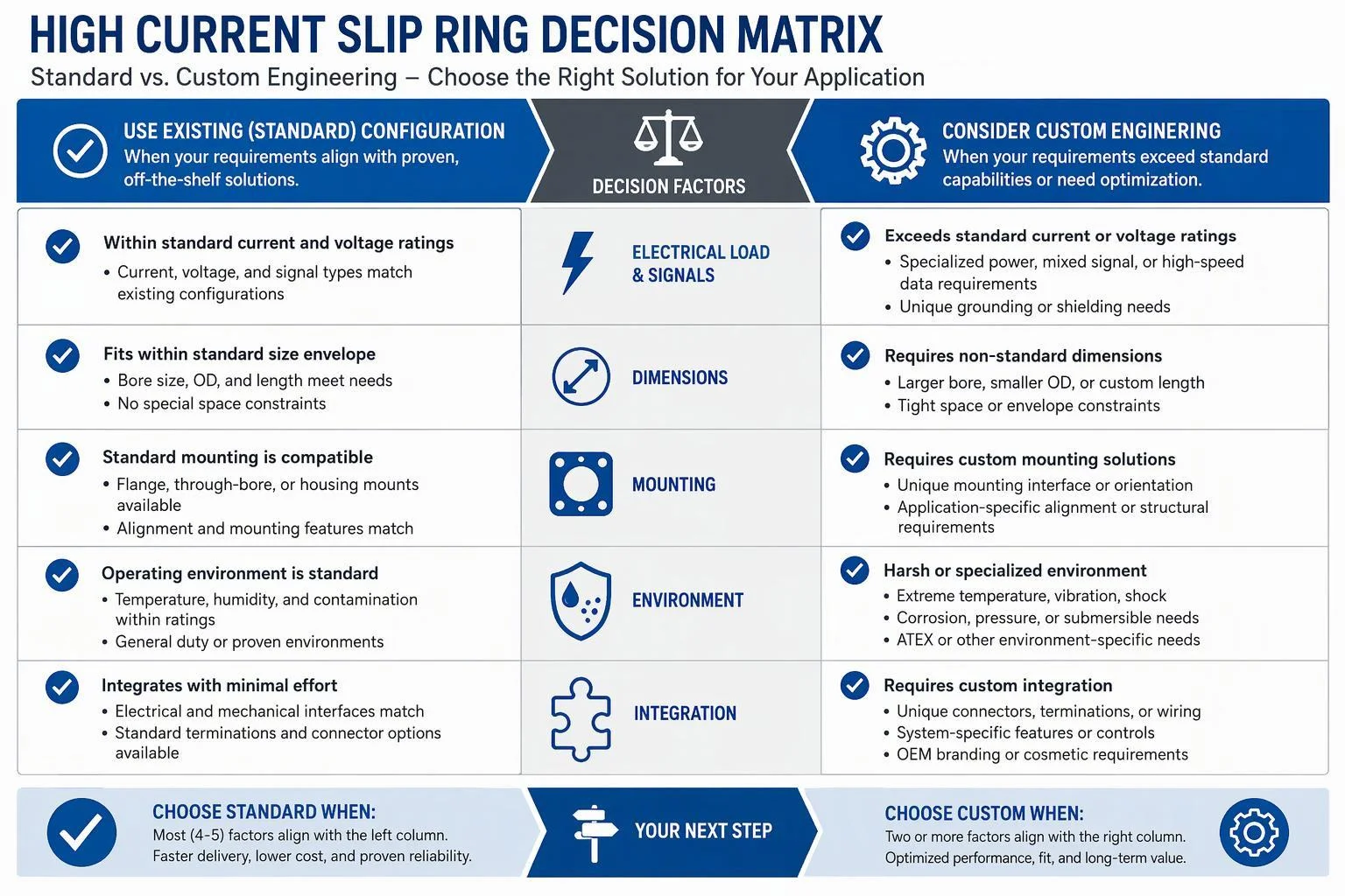
A custom review needs a circuit table, current and voltage requirements, load profile, mechanical drawing, installation envelope, rotational requirements, environmental requirements, signal and communication requirements, and project quantity and stage. The same package supports a standard evaluation, so prepare it once.
10. What Testing and Validation Should Be Defined Before Ordering?
Project-specific validation requirements should be discussed before quotation and design approval. Depending on the application, engineers may need electrical, thermal, mechanical, signal, environmental, or documentation checks. The exact test methods and acceptance criteria should come from the project specification, applicable standards, and supplier documentation rather than being assumed.
Electrical Verification
Define continuity, circuit identification, insulation requirements, dielectric requirements where specified, grounding checks, and your own electrical acceptance criteria. State which values come from your machine specification so the supplier is not left to choose them.
Thermal Verification
Where temperature-rise evaluation is required, define representative electrical loading, the relevant ambient conditions, measurement locations, and acceptance criteria. A temperature-rise test only means something when the loading and ambient conditions it represents are stated.
Mechanical Verification
Mechanical verification covers dimensions, mounting interface, rotational performance, and cable and terminal arrangement. Confirm these against the interface drawing before design approval, because mechanical corrections after tooling are costly.
Signal Verification
Signal verification covers communication functionality, signal integrity where relevant, and mixed power-and-signal operation under loaded conditions. Define acceptance criteria with the protocol owner rather than accepting a generic pass result.
Environmental Verification
Environmental verification may include required environmental testing, customer-defined IP or ingress requirements, vibration or shock where applicable, and application-specific validation. Tie severity and duration to your project specification or applicable standard, not to a default.
Documentation
Request drawings, circuit diagrams, terminal pinouts, inspection records and test reports where the project requires them, plus product identification for traceability.
11. What Should OEMs Evaluate When Comparing High Current Slip Ring Suppliers?
Supplier comparison should test whether a supplier can read and respond to your specification, not whether its catalogue lists a large current figure. Compare how each supplier reviews circuits, documents the configuration, handles change, and supports the unit after delivery.
Application and Engineering Review
Ask whether the supplier reviews current circuit by circuit, discusses the load profile, checks mechanical integration, and addresses mixed power and signal and environmental requirements before quoting.
Documentation Quality
Ask for the drawing set, circuit schedule, terminal or pinout information, installation guidance and configuration records, and confirm that the documents you receive match the configuration you approve.
Testing and Quality Control
Request the inspection and validation documentation relevant to your project, and confirm which electrical and mechanical checks are performed on the actual configuration.
Change Control and Customization
Establish how electrical, mechanical, cable and terminal changes are recorded, approved and reflected in configuration records before production begins.
Lifecycle Support
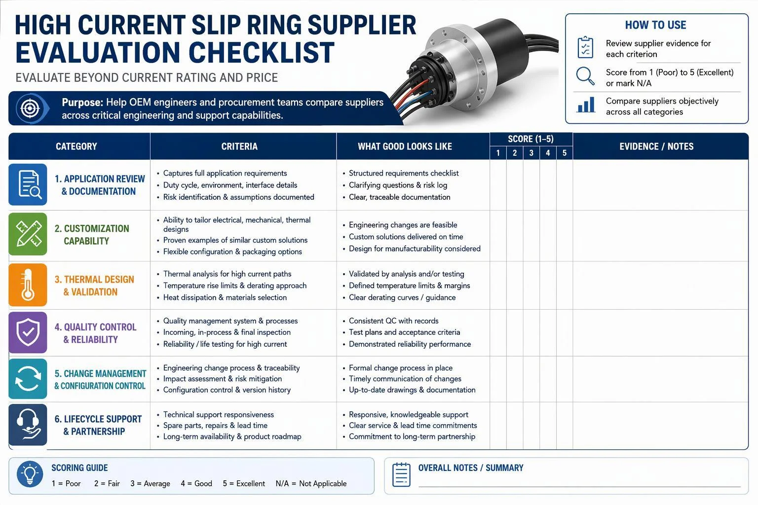
Discuss maintenance guidance, spare-unit strategy, replacement planning and technical communication, and align the project schedule with the supplier early.
12. What Are the Most Common High Current Slip Ring Selection Mistakes?
Common high current slip ring selection mistakes usually come from incomplete load information or from treating the current rating as an isolated number. OEM engineers should define the real operating profile, thermal environment, mechanical conditions, mixed-signal requirements, and installation constraints before approving a high current slip ring. Writing those requirements into the specification converts each mistake below into a question with a documented answer.
Specifying Only Total Current
A single total hides how current divides across circuits; specify current per circuit instead.
Ignoring Current Per Circuit
Without per-circuit values, the supplier cannot size individual paths or evaluate local heating.
Using Maximum Current Without Describing Duration
A maximum with no duration cannot be converted into a thermal load; state how long it lasts.
Omitting Peak or Inrush Current
Motor starting and similar events stress contacts; record magnitude, duration and repetition.
Ignoring Simultaneous Circuit Loading
Circuits loaded together share a thermal environment; state which ones run at the same time.
Ignoring Ambient Temperature and Heat Dissipation
Ambient heat and restricted airflow reduce available margin; describe the real installation.
Choosing an IP Rating Without Describing the Environment
An IP number alone omits chemicals, salt and cleaning; describe the exposure itself.
Specifying Maximum RPM Without Duty Cycle
Speed without duty cycle says little about wear; add continuous or intermittent rotation and start-stop frequency.
Adding Signals or Data After the Power Architecture Is Finalized
Late signal additions force rework of routing, shielding and grounding; define channels and protocols early.
Providing Dimensions Without a Mounting Drawing
Envelope dimensions do not show flange, bore or cable exit; send an interface drawing.
Introducing Testing Requirements After Design Approval
Late test requirements can invalidate an approved design; state validation needs before approval.
13. What Information Should Be Included in a High Current Slip Ring RFQ?
A complete RFQ lets the supplier review the application as one integrated rotating system. The six groups below cover what to send.
Electrical Information
Circuit quantity, current per circuit, continuous current, peak or inrush current with duration and repetition, voltage, AC or DC, simultaneous loading, and grounding and isolation requirements.
Signal and Data Information
Signal types, communication protocols, channel quantity, shielding and grounding expectations, and any performance requirements the machine imposes.
Mechanical Information
Maximum dimensions, through-bore or shaft requirements, mounting interface, rotational speed, duty cycle, cable exit and terminal requirements, and a mechanical drawing where available.
Environmental Information
Ambient temperature, dust, water, corrosion, chemicals, vibration, outdoor or marine exposure, and any special project requirements.
Validation and Documentation
Required testing, required reports, drawings, inspection requirements, and compliance documentation where the project calls for it.
Project Information
Prototype or production stage, quantity, project schedule, requested quotation scope, and spare-unit requirements where relevant.
14. High Current Slip Ring Selection Checklist
Use this checklist to confirm the minimum information an OEM engineer should have in hand before selecting a high current slip ring or submitting an RFQ. An unchecked box is a question the supplier will have to ask, and each round of questions adds time before a configuration can be evaluated.
Electrical Checklist
Circuit quantity defined
Current per circuit defined
Continuous current defined
Peak or inrush current defined where relevant
Load duration and repetition defined
Voltage defined
AC or DC operation defined
Simultaneous loading defined
Grounding and isolation requirements defined
Thermal Checklist
Ambient conditions defined
Enclosed or ventilated installation identified
Nearby heat sources identified
Thermal acceptance requirements identified where applicable
Mechanical Checklist
Rotational speed defined
Duty cycle defined
Installation envelope defined
Bore or shaft requirement defined
Mounting interface defined
Cable and terminal arrangement defined
Drawing attached where available
Environmental Checklist
Temperature requirement defined
Dust and water exposure defined
Corrosion or chemical exposure defined
Vibration and shock conditions defined
Project-specific protection requirements defined
Signal and Validation Checklist
Signal types defined
Communication protocols defined
Shielding requirements defined
Required testing defined
Required documentation defined
Project Checklist
Standard versus custom requirement reviewed
Prototype quantity defined
Production quantity defined
Project schedule provided
RFQ scope clearly stated
15. How Can JINPAT Support a High Current Slip Ring Selection Project?
JINPAT is the engineering contact to approach once the electrical, thermal, mechanical, environmental, and signal requirements are defined. JINPAT has worked in slip ring design and manufacturing since 1996, and its high current integrated slip ring line combines power and signal channels in one assembly, with current capacity, circuit configuration, speed, temperature, and protection level open to customization.
Application Requirement Review
Submit circuit-level current and voltage requirements together with the load profile, motion profile, environment, and mechanical constraints. Drawings help even at sketch stage, because mounting side, bore, and cable exit often decide whether an existing configuration can be adapted at all.
Standard or Custom Configuration Discussion
JINPAT reviews the submitted circuit table, load profile and drawings against available configurations, then indicates whether a standard high current slip ring may fit or whether application-specific engineering should be discussed.
Next-Step Options
Submit your high current slip ring requirements for an application review, send your electrical specification and mechanical drawing, request a product recommendation based on operating conditions, or request a quotation for a defined standard or custom configuration.
16. Frequently Asked Questions About High Current Slip Ring Selection
Each answer below stands on its own, so you can lift one into a specification review or an internal design note without the surrounding text.
What Information Is Most Important When Selecting a High Current Slip Ring?
Current per circuit, continuous and peak loading, voltage, circuit count, load profile, thermal conditions, rotational duty, mechanical integration, and environment matter most. A high current slip ring cannot be specified from a single headline ampere figure, because the same total current distributed across different circuits and duty cycles produces different thermal and contact conditions.
Should I Specify Continuous and Peak Current Separately?
Yes. Continuous and peak current stress the rotating interface differently, so magnitude, duration, and repetition should be stated separately. A brief high peak and a long moderate overload can lead to different conductor, contact, and thermal design choices.
Is Total Current Enough to Select a High Current Slip Ring?
No. Total current hides how the load is distributed. Current per circuit, how many circuits are energized at once, and whether loads overlap in time all affect local heating and contact loading, so a 600 A total split as six 100 A circuits is not equivalent to two 300 A circuits.
How Does Ambient Temperature Affect High Current Slip Ring Selection?
Ambient temperature sets how much thermal margin remains after the slip ring's own losses, so it belongs in the engineering review alongside the electrical load. A configuration that performs acceptably in a ventilated cabinet may not do so inside a closed housing next to a motor; the review should assess the actual installation rather than apply a fixed derating percentage.
Can High Current and Data Signals Be Combined in One Slip Ring?
Combined transmission may be possible depending on the design, but it is not automatic. Signal type, protocol, channel count, separation from power circuits, shielding, grounding, and the overall electrical architecture should be defined so the supplier can judge whether the combination is workable.
When Should an OEM Consider a Custom High Current Slip Ring?
An OEM should consider a custom high current slip ring when no existing configuration meets the electrical, signal, dimensional, mounting, environmental, or integration requirements. Custom engineering is justified by a specific gap, not by preference, and the gap should be documented in the specification.
What Should I Send to a Supplier for a High Current Slip Ring Quote?
Send the electrical load profile by circuit, a mechanical drawing, speed and duty cycle, environment, signal requirements, validation requirements, quantity, and project schedule. Suppliers can quote faster and more accurately when the application is described as a complete system rather than a single current figure.
Conclusion: Build the High Current Slip Ring Specification Around the Real Load Profile
Build the high current slip ring specification in this order: define current per circuit and the load profile, then voltage and circuit architecture, then thermal conditions, rotational and mechanical requirements, environment and signal requirements, the standard-versus-custom decision, and validation requirements. Only then prepare the RFQ and request engineering review. The headline current rating is one input to that sequence, never the basis for selection on its own.
To move forward, submit your high current slip ring specifications and drawings to JINPAT for an application review. If the requirements are already firm, request a product recommendation or quotation based on your electrical, thermal, mechanical, environmental, and project requirements.
Name
Email*
*Phone
Application
Message
*

